Electric connector for circuit substrate
A technology of circuit substrates and electrical connectors, which is applied in the direction of circuits, connections, components of connection devices, etc., can solve the problems of inability to reduce the back of terminals, etc., to ensure high-speed transmission characteristics, improve operability, and prevent high-speed transmission characteristics Reduced effect
- Summary
- Abstract
- Description
- Claims
- Application Information
AI Technical Summary
Problems solved by technology
Method used
Image

Examples
no. 1 approach
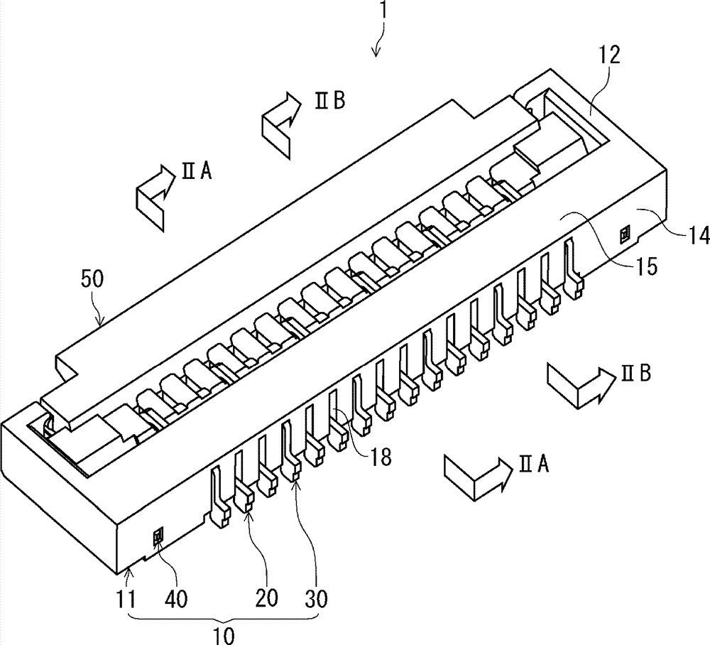
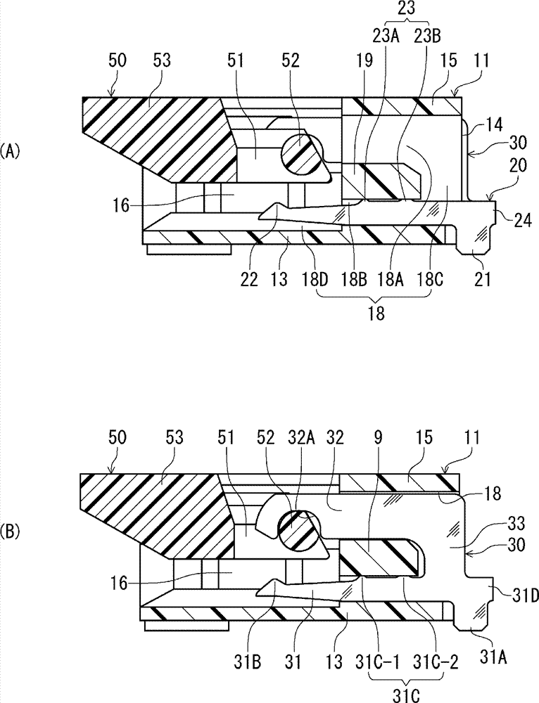
[0029]figure 1 It is an overall perspective view of the circuit board connector of this embodiment. figure 2 (A) is figure 1 IIA-IIA sectional view of the connector, showing a section at the position of the first terminal, figure 2 (B) is figure 1 IIB-IIB sectional view of the connector, showing a section at the position of the second terminal.
[0030] The circuit board connector 1 of this embodiment (hereinafter referred to as "connector 1") is arranged on a circuit board (not shown) and viewed from the rear (in the figure 1 The connector for high-speed transmission for connecting a flat conductor (not shown) has a connector body 10 and a movable member 50 supported by the connector body 10 so as to be rotatable. The movable member 50 is rotatable between an open position for inserting the flat conductor into the connector body 10 from the rear toward the front, and a closed position for pressing the inserted flat conductor. exist figure 1 In , the movable member 50 i...
no. 2 approach
[0069] Figure 5 The first terminal 60 according to the present embodiment shown is at a point above the upper edge of the intermediate portion of the first terminal 60 and above the press-fit protrusion 63 at the cut end surface of the pallet separating portion 64 , and is aligned with the pallet. The structure of the first embodiment is different in that the upper end of the cut end surface of the separating portion is located at the same position as the upper edge of the intermediate portion, and the cut end surface is located at a position extending downward from the upper edge. Since the first terminal 60 of this embodiment is formed in the same shape as the first terminal 20 of the first embodiment except for the pallet separating portion 64, the parts other than the pallet separating portion 64 are marked as the above-mentioned first terminal. The corresponding part of 20 is added with the reference numeral "40", and description is omitted. In addition, since the casin...
no. 3 approach
[0074] Image 6 In the present embodiment shown in (A) and (B), the rear abutment surface 75A is formed on the first terminal 70 as a portion that abuts against the fixing portion 19 of the housing 11 from the front and positions the first terminal 70 in the front-rear direction. The terminal 70 differs from the structure of the first embodiment in that there is no portion abutting on the fixing portion 19 from the front. Since the first terminal 70 of this embodiment is formed in the same shape as the first terminal 20 of the first embodiment except for the pallet separating portion 74, the parts other than the pallet separating portion 74 are denoted by the above-mentioned first terminal 20. The corresponding part adds the reference sign of "50" and omits description. In addition, since the casing 11 and the movable member 50 of this embodiment have completely the same structure as that of the first embodiment, the same reference numerals as those of the first embodiment ar...
PUM
 Abstract
Description
Claims
Application Information
 - R&D
- Intellectual Property
- Life Sciences
- Materials
- Tech Scout
- Unparalleled Data Quality
- Higher Quality Content
- 60% Fewer Hallucinations
Browse by: Latest US Patents, China's latest patents, Technical Efficacy Thesaurus, Application Domain, Technology Topic, Popular Technical Reports.
© 2025 PatSnap. All rights reserved.Legal|Privacy policy|Modern Slavery Act Transparency Statement|Sitemap|About US| Contact US: help@patsnap.com