Method for automatically testing optical link in passive optical network

A passive optical network and automatic test technology, applied in the field of passive optical network, can solve the problems of high difficulty, misjudgment of optical link failure, high network operation and maintenance cost, so as to improve operation and maintenance efficiency and reduce operation and maintenance cost Effect

Active Publication Date: 2012-10-17
FENGHUO COMM SCI & TECH CO LTD
View PDF2 Cites 37 Cited by
  • Summary
  • Abstract
  • Description
  • Claims
  • Application Information

AI Technical Summary

Problems solved by technology

The OTDR test is the most common method for optical link detection. The traditional analysis method for OTDR test results is to analyze various link events in the OTDR test curve, such as reflective surfaces, fusion splices, macrobends, and even ghosts, etc. , this analysis method is very difficult to summarize into an algorithm, and the accuracy rate is not ideal when it is applied to automatic testing
[0006] 2. The passive optical network is a point-to-multipoint topology. When the main optical link is abnormal, it will affect the display of the branch optical link in the OTDR test curve, which may easily lead to misjudgment of optical link failure.
[0007] 3. Each optical link OTDR test requires manual intervention and subjective judgment and analysis of the test results, resulting in lower O&M efficiency of passive optical networks and high network O&M costs

Method used


Image

  • Method for automatically testing optical link in passive optical network
  • Method for automatically testing optical link in passive optical network
  • Method for automatically testing optical link in passive optical network

Examples


Embodiment Construction

[0030] The present invention will be further described in detail below in conjunction with the drawings and specific embodiments.

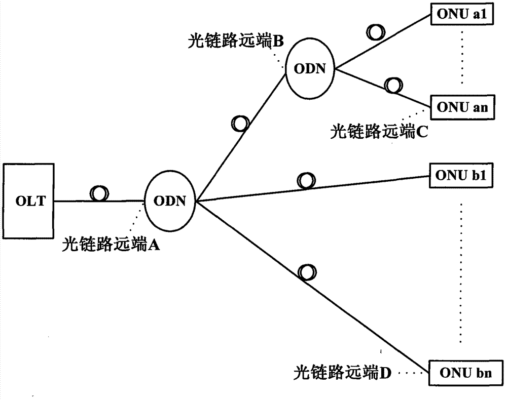
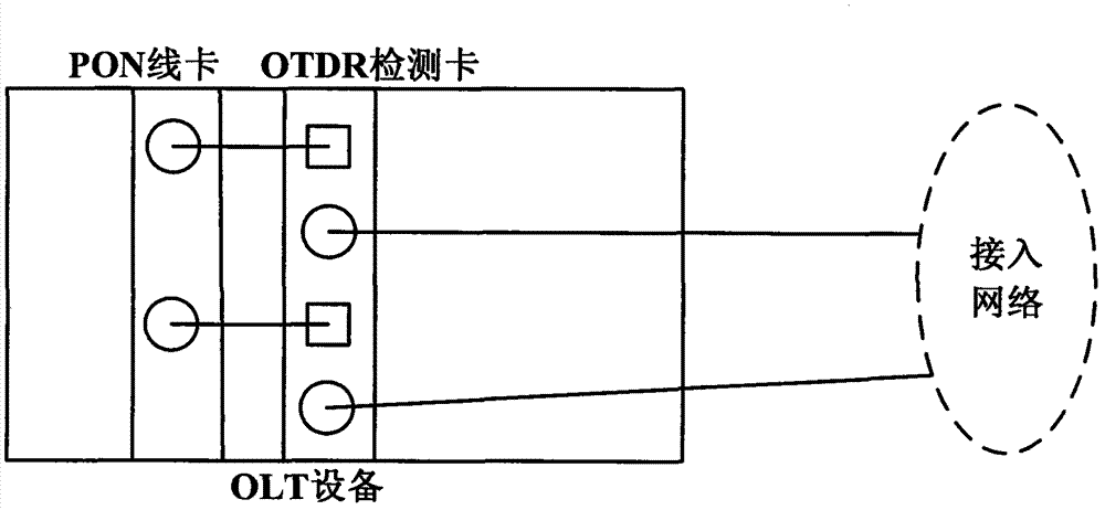
[0031] See figure 1 As shown, in the topological structure of the passive optical network, the central office equipment OLT respectively communicates with the optical link remote B (ODN) and the optical link remote D (ONU b1, b2) through the optical link remote A (ODN). ...Bn) is connected, and the optical link remote B (ODN) is connected to the optical link remote C (ONU a1, a2...an), and n is an integer greater than 2. Among them, the central office equipment OLT is integrated with an OTDR detection card, see figure 2 As shown, in the OLT equipment with integrated OTDR detection card, the optical fiber is led out from the PON port of the OLT business line card, enters the input port of the OTDR board, and then is led out from the corresponding output port of the OTDR board, and connected to the access network .

[0032] The principle of the embodim...


PUM


Abstract

The invention discloses a method for automatically testing an optical link in a passive optical network, and relates to the field of passive optical networks. The method comprises the following steps: setting an optical time domain reflectometry (OTDR) test parameter of the optical link, acquiring and setting a standard OTDR test curve and a standard OTDR curve reference point of the optical link, and establishing a relation of the actual optical link and the standard OTDR curve reference point; acquiring an OTDR test curve of the optical link; comparing the test curve and the standard test curve; checking the state of the optical link, and if an abnormal reference point exists, finding out the abnormal optical link according to the corresponding relation of the reference point and the optical link; and performing 'trunk-branch' fault judgment on the abnormal optical link by using the topological structure of the passive optical network, deleting a mis-reported abnormal branch optical link, finding out a fault point of the optical link according to a new event point on the curve, and reporting the optical link test result. According to the method, artificial participation and judgment during detection of the optical link are avoided; the operation and maintenance efficiency of the passive optical network can be improved; and the operation and maintenance cost is reduced.

Description

Technical field [0001] The present invention relates to the field of passive optical networks, in particular to a method for automatically testing optical links in passive optical networks. Background technique [0002] PON (Passive Optical Network, passive optical network) technology is a broadband access technology with advantages such as large capacity, long transmission distance, low cost, and full service support. The three main parts of the passive optical network include the OLT (Optical Line Terminal) at the central office, the ONU (Optical Network Unit) at the terminal, and the ODN (Optical Distribution Unit) that connects the OLT and the ONU. Network, Optical Distribution Network). The "passive" in the "passive optical network" means that the ODN is entirely composed of passive components such as optical splitters (Splitter) and does not contain any electronic components and power supplies. [0003] OTDR (Optical Time Domain Reflectometer) is currently the most commonly...

Claims


Application Information

Patent Timeline
IPC IPC(8): H04B10/08H04B10/12H04Q11/00
Inventor 康磊熊伟成王素椅张超
Owner FENGHUO COMM SCI & TECH CO LTD
Why Eureka
Try Eureka