Mobile solar power-generating system

A power generation system, solar technology, applied in the field of mobile solar power generation systems, can solve problems such as difficulty, waste of time, and discomfort

Inactive Publication Date: 2012-10-17
PRO D3
View PDF6 Cites 16 Cited by
  • Summary
  • Abstract
  • Description
  • Claims
  • Application Information

AI Technical Summary

Problems solved by technology

Even if this deployment method can be done by one person, it is not easy, uncomfortable and time consuming

Method used


Image

  • Mobile solar power-generating system
  • Mobile solar power-generating system
  • Mobile solar power-generating system

Examples


Embodiment Construction

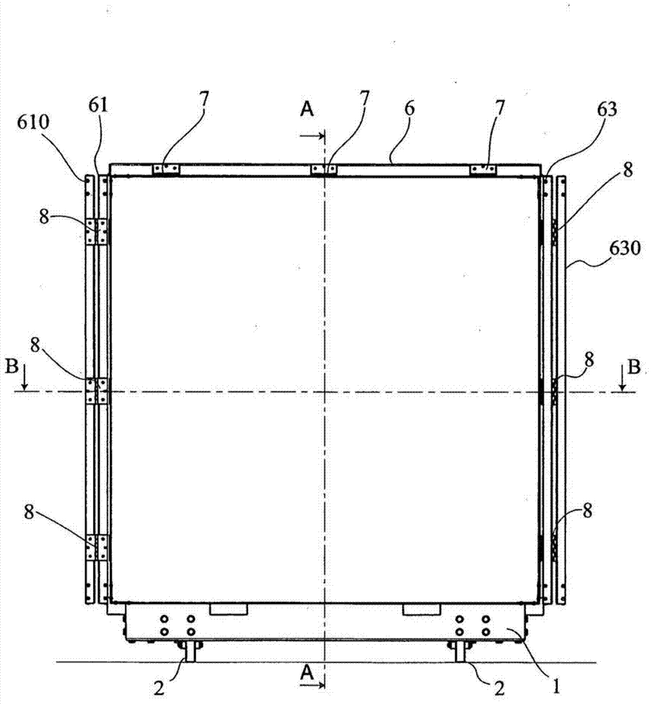
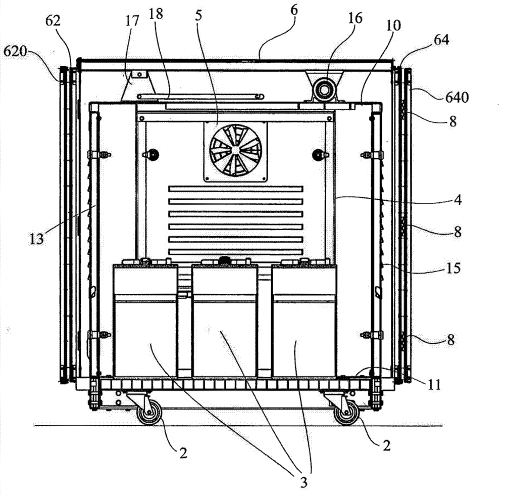
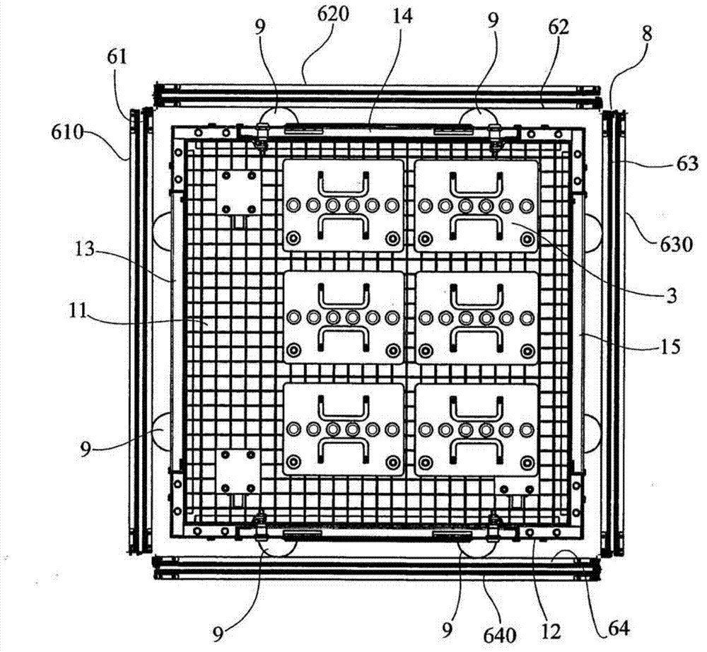
[0017] First, refer to Figure 1 to Figure 5 , wherein various views and various cross-sectional views show a power generation system according to the invention. In particular, in the front view of figure 1 Among them, what is marked as 1 is the box, on which there are wheels usually marked as 2. figure 1 Formed along the lines A-A and B-B respectively in figure 2 and image 3 The sectional view of FIG. 1 shows the box 1 in more detail, which is prismatic and has a top wall 10 , a bottom wall 11 and side walls 12 , 13 , 14 and 15 . Shown inside the box 1 are a number of accumulators, generally designated 3, and a housing 4 for the electrical generation system wiring. The casing 4 is provided with a fan 5 . The central photovoltaic panel 6 is supported on the top wall 10 in a tiltable manner by support means as described below. Hinged to each side of the central photovoltaic panel 6 by cylindrical hinges 7 are respective transverse photovoltaic panels 61 , 62 , 63 , 64 w...


PUM


Abstract

A mobile solar power-generating system comprises a prismatic container (1) having a top wall (10), a bottom wall (11) and side walls. A central photovoltaic panel (6) is supported in a tiltable manner on the top wall (10) by supporting means, on each of the sides of the central photovoltaic (6) being hinged a correspondent transversal ph tovoltaic panel (61, 62, 63, 64) hanging downward in a rest position and being able to rotate 90 degrees upward. On a side of each transversal photovoltaic panel (61, 62, 63, 64) is hinged a side photovoltaic panel (610, 620, 630, 640) that is designed to fold down with respect to the relevant transversal photovoltaic panel (61, 62, 63, 64).; Mutual engagement means are provided for keeping coplanar the transversal photovoltaic panels (61, 62, 63, 64) and the side photovoltaic panels (610, 620, 630, 640) to the central photovoltaic panel (6) when the power-generating system is in an operating position.

Description

technical field [0001] The invention relates to a mobile solar power generation system. Background technique [0002] Such power generation systems are known. For example, patent application RM2006A000294 relates to a solar energy conversion portable (helitransportable) self-powered device, which includes a box, a telescopic pole capable of supporting a solar panel, and is designed so that the telescopic pole is manually mounted to the vertical rear of the box. An extension device on the wall to extend the telescoping rod afterwards. The solar panel must be removed from the box and positioned on the telescoping pole by the solar panel holding arm supported by the telescoping pole. Even though this deployment can be done by one person, it is not easy, uncomfortable and time consuming. [0003] In view of this, the technical task of the present invention is to provide a mobile solar power generation system, which overcomes the above-mentioned shortcomings of the prior art. ...

Claims


Application Information

Patent Timeline
Patent Type & Authority Applications(China)
IPC IPC(8): H01L31/045H02S30/20
CPCH01L31/045F24J2/541F24J2002/5486Y02E10/50H02S30/20F24S2025/012F24S2030/16F24S30/425
Inventor S·塞尔吉奥蒂乌齐菲·马可S·安德烈亚
Owner PRO D3
Why Eureka
Try Eureka