Motor load distribution control method and motor load distribution control device

A technology of load distribution and control method, applied in the direction of roll speed control, etc., can solve the problems of unbalanced motor load, mechanical vibration, affecting rolling efficiency and finished product quality, etc., and achieve the effect of ensuring rolling efficiency and finished product quality.

Active Publication Date: 2012-10-24
北京景新电气技术开发有限责任公司
View PDF4 Cites 7 Cited by
  • Summary
  • Abstract
  • Description
  • Claims
  • Application Information

AI Technical Summary

Problems solved by technology

[0003] In the actual rolling process, due to the influence of factors such as the difference in the diameter of the upper and lower work rolls, the friction system between the strip steel and the work roll surface, etc., the load of the drive motor of the upper and lower rolls is unbalanced, which in turn causes the surface friction between the work roll and the strip steel. Relative sliding occurs, causing overheating of the motor and mechanical vibration in severe cases, thus affecting rolling efficiency and product quality

Method used


Image

  • Motor load distribution control method and motor load distribution control device
  • Motor load distribution control method and motor load distribution control device
  • Motor load distribution control method and motor load distribution control device

Examples


Embodiment 1

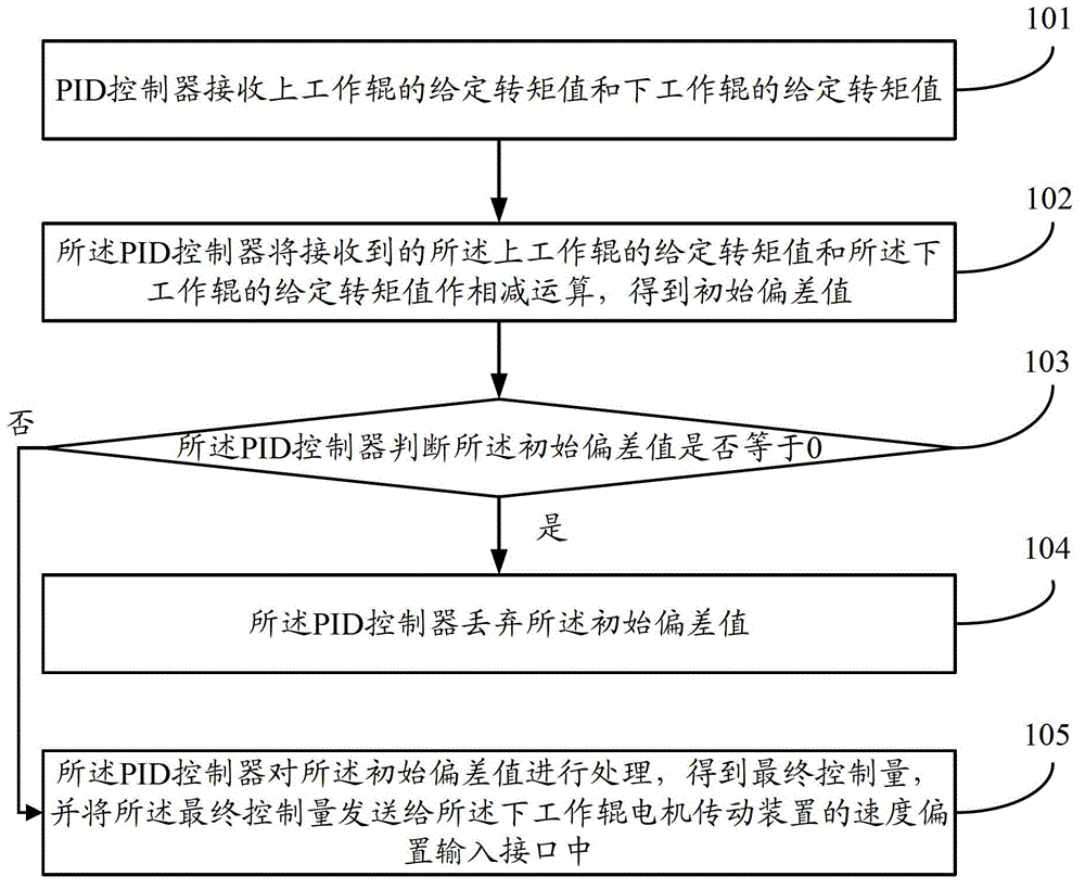
[0044] Such as figure 1 As shown, it is a schematic flowchart of a motor load distribution control method provided by an embodiment of the present invention, including the following steps:

[0045] Step 101, the PID controller receives the given torque value of the upper work roll and the given torque value of the lower work roll.

[0046] Specifically, the PID controller respectively receives the given torque value of the upper work roll sent by the upper work roll motor drive through the field bus and the given torque of the lower work roll sent by the lower work roll motor drive through the field bus value.

[0047] In addition, the PID controller can receive the given torque value of the upper work roll and the given torque value of the lower work roll according to the preset frequency. Make sure.

[0048] Step 102, the PID controller subtracts the received given torque value of the upper work roll and the given torque value of the lower work roll to obtain an initial d...

Embodiment 2

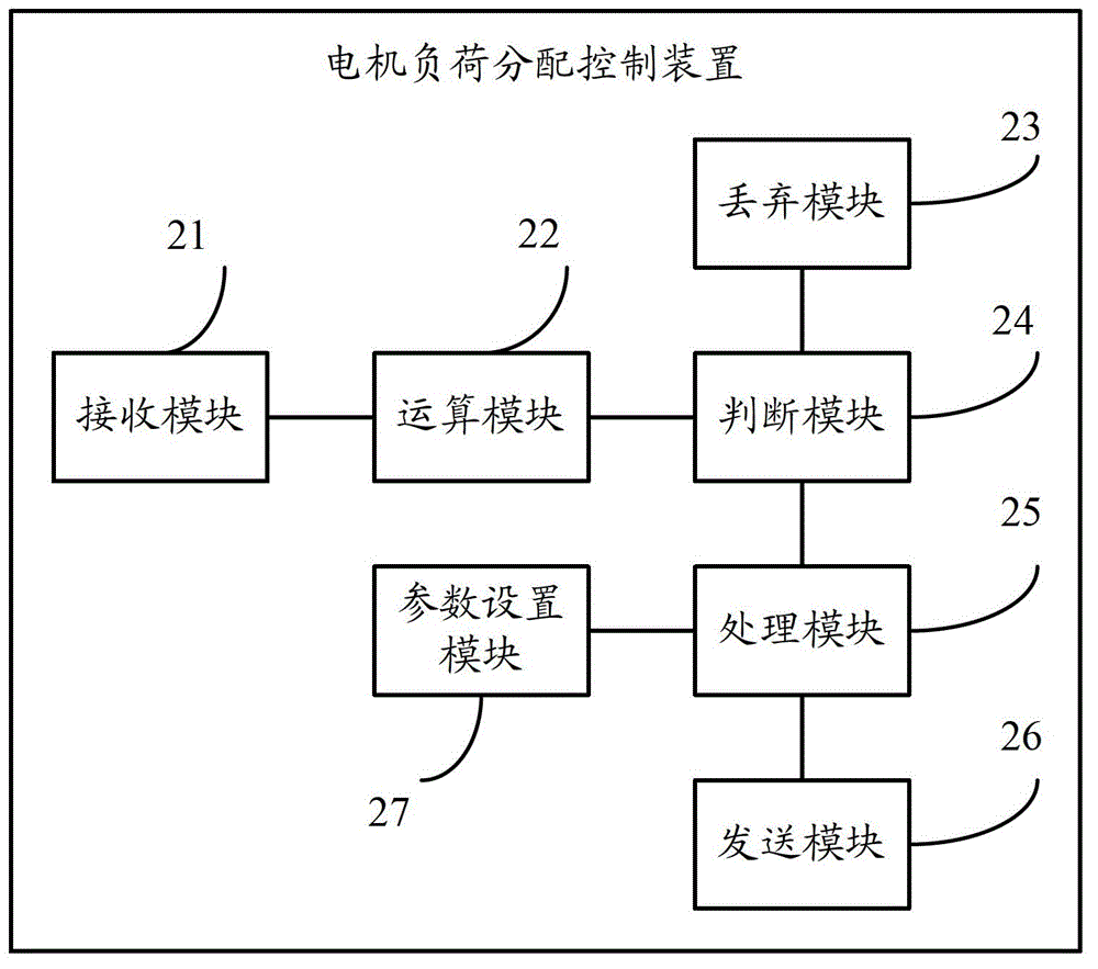
[0061] Such as figure 2 As shown, it is a schematic structural diagram of a motor load distribution control device provided by an embodiment of the present invention. The motor load distribution control device is a PID controller, and the PID controller includes the following modules:

[0062] A receiving module 21, configured to receive a given torque value of the upper work roll and a given torque value of the lower work roll;

[0063] The receiving module is also used to: respectively receive the given torque value of the upper work roll sent by the upper work roll motor drive through the field bus and the given torque of the lower work roll sent by the lower work roll motor drive through the field bus value.

[0064] An arithmetic module 22, configured to subtract the given torque value of the upper work roll received by the receiving module 21 from the given torque value of the lower work roll to obtain an initial deviation value;

[0065] A judging module 23, configur...


PUM


Abstract

The invention provides a motor load distribution control method and a motor load distribution control device. A difference value of a given torque value of an upper work roller and a given torque vale of a lower work roller are used as the input of a PID (proportion integration differentiation) controller, the output of the PID controller is used as the speed of the lower work roller to realize the additional giving, the goal of regulating the upper and lower work roller load distribution is reached through regulating the speed of the lower work roller, and further, the load balance effect of upper and lower roller transmission motors is realized, so the rolling efficiency and the finished product quality of the steel rolling process are ensured.

Description

technical field [0001] The invention belongs to the technical field of motor load control, and in particular relates to a motor load distribution control method and device. Background technique [0002] In the existing single-stand reversible six-high cold rolling mill, the transmission system of the rolling mill usually adopts the mode of independent transmission of the upper and lower work rolls, and reasonably distributes the rolling load to the drive motors of the upper and lower rolls; among them, the upper work roll and the upper work roll The roller transmission motor is connected, and the lower working roll is connected with the lower roller transmission motor. [0003] In the actual rolling process, due to the influence of factors such as the difference in the diameter of the upper and lower work rolls, the friction system between the strip steel and the work roll surface, etc., the load of the drive motor of the upper and lower rolls is unbalanced, which in turn ca...

Claims


Application Information

Patent Timeline
IPC IPC(8): B21B37/46
Inventor 于红
Owner 北京景新电气技术开发有限责任公司
Why Eureka
Try Eureka