Tank erecting device for continuous sterilization machine

A technology for sterilizers and vertical tanks, which is applied in the direction of conveyor objects, transportation and packaging, etc. It can solve the problems of insufficient tank processing capacity, difficulty in meeting the continuity of continuous sterilization and mass production, and unreasonable structural design.

Active Publication Date: 2012-10-24
山东鼎泰盛机械科技有限公司
View PDF7 Cites 5 Cited by
  • Summary
  • Abstract
  • Description
  • Claims
  • Application Information

AI Technical Summary

Problems solved by technology

[0002]The continuous sterilizer performs secondary sterilization on the cans filled with food, beverages or pharmaceuticals, and then outputs them, and then carries out subsequent processes such as labeling, spraying and packaging on the cans , because the process of labeling, spraying and packaging needs to be carried out in an upright state of the tank, due to the continuity and large-scale nature of continuous sterilization, the number of tanks in the sink is extremely large and in an irregular scattered state, such as Outputting the water tank in the above state for subsequent processing will greatly increase the processing difficulty and labor intensity of the subsequent process, and the efficiency is low. Therefore, it is necessary to straighten out the tanks in the scattered state and then output them to the water tank, and then go through vertical tanks, collection and normalization. After anti-recognition and correction, the processes of marking, spraying and packaging are carried out to facilitate the processing of subsequent processes and improve production efficiency
However, most of the existing devices for vertical tanks are not designed properly, the tank processing capacity is insufficient, the operation and transportation of vertical tanks are not smooth enough, and it is difficult to meet the continuity of continuous sterilization and the requirements of mass production , reducing production efficiency

Method used


Image

  • Tank erecting device for continuous sterilization machine
  • Tank erecting device for continuous sterilization machine
  • Tank erecting device for continuous sterilization machine

Examples


Embodiment Construction

[0021] Below in conjunction with accompanying drawing and embodiment, further elaborate the present invention. In the following detailed description, certain exemplary embodiments of the invention are described by way of illustration only. Needless to say, those skilled in the art would realize that the described embodiments can be modified in various different ways, all without departing from the spirit and scope of the present invention. Accordingly, the drawings and description are illustrative in nature and not intended to limit the scope of the claims.

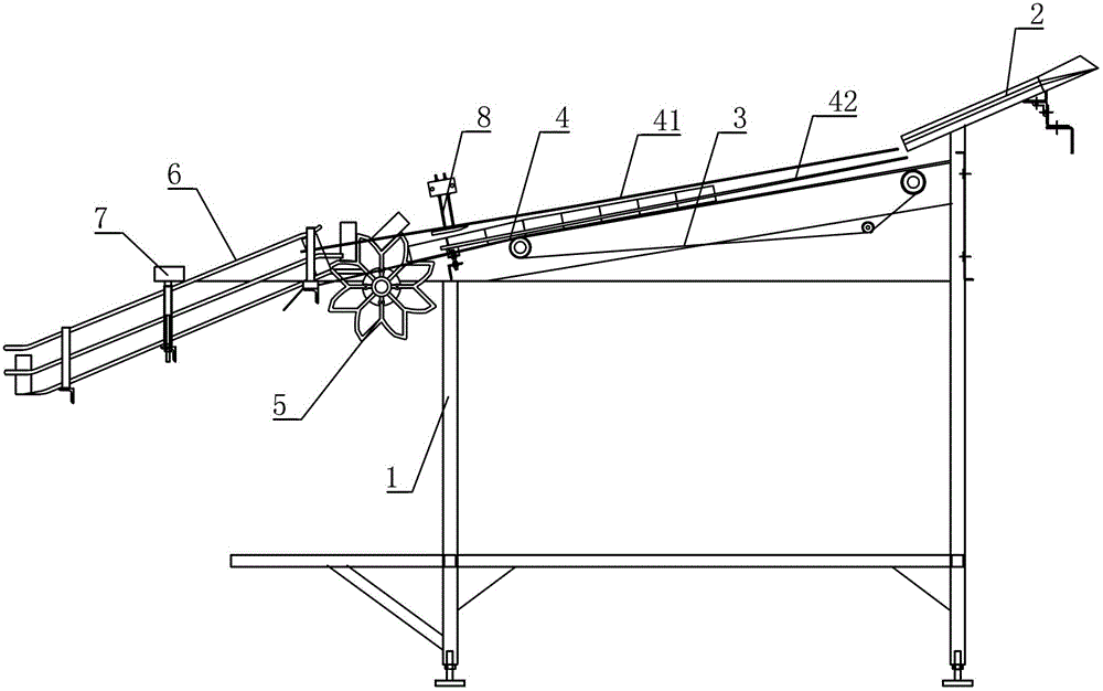
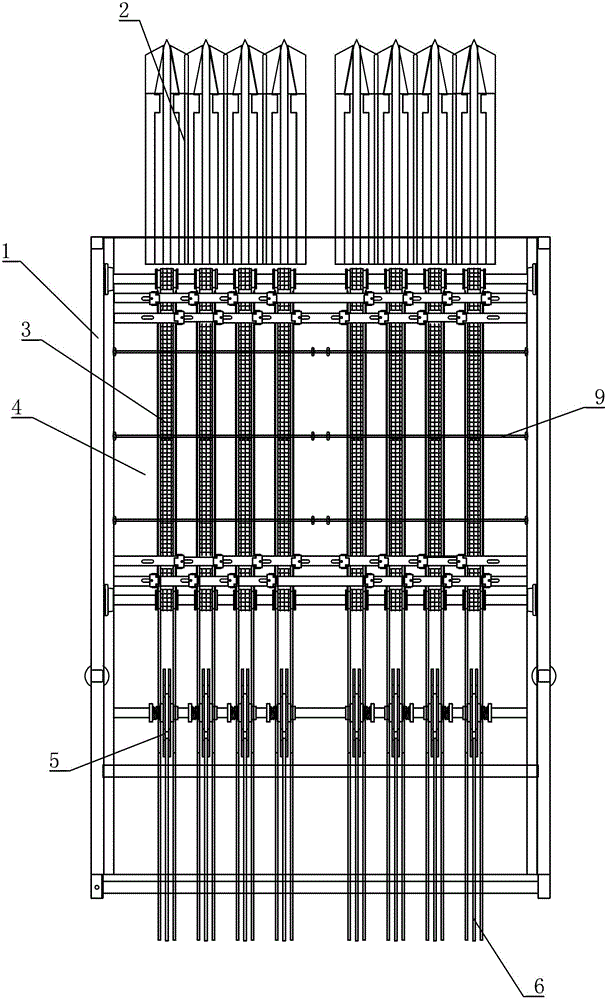
[0022] like figure 1 and figure 2 As shown, the vertical tank device for the continuous sterilizer includes a frame 1, and the frame 1 is inclined to be provided with a tank outlet chute 2, and the input slot of the tank outlet chute 2 is higher than the output slot, so The output slot of the tank chute 2 is provided with a tank belt 3, the input end of the tank belt 3 is located below the output slot of the tank chut...


PUM


Abstract

The invention discloses a tank erecting device for a continuous sterilization machine. The tank erecting device comprises a stander, wherein a tank discharge sliding chute is obliquely arranged on the stander, an input chute opening of the tank discharge sliding chute is higher than an output chute opening, a tank conveying belt is arranged at the output chute opening of the tank discharge sliding chute, an input end of the tank conveying belt is positioned below an output chute opening of the tank discharge sliding chute, an output end of the tank conveying belt is provided with a tank erecting device for erecting tanks, an output end of the tank erecting device is provided with a tank sliding frame for conveying the erected tank bodies, a tank guide device is arranged above the tank conveying belt, and the tank conveying belt is connected with a tank-erecting power device. The tank erecting device disclosed by the invention has the advantages of reasonable structure, high tank body processing capability, smoothness in tank erecting operation and conveyance of the tank bodies and capability of meeting continuous sterilization continuity and large-batch production.

Description

technical field [0001] The invention relates to the technical field of light industry machinery, in particular to a vertical can device for continuous sterilizers used for erecting and arranging tanks on continuous sterilizers in industries such as filling food, beverages or pharmaceuticals. Background technique [0002] The continuous sterilizer sterilizes the cans filled with food, beverages or pharmaceuticals for the second time, and then outputs the cans, and then performs subsequent labeling, spraying, and packaging processes on the cans. The process of labeling, spraying, and packaging needs to be done in an upright position on the tank body. Due to the continuity and large-scale nature of continuous sterilization, the number of tanks in the tank is extremely large and in an irregular scattered state. If the tank is output in the above-mentioned state for subsequent processing, it will greatly aggravate the follow-up process. The process is difficult, labor-intensive, ...

Claims


Application Information

Patent Timeline
Patent Type & Authority Applications(China)
IPC IPC(8): B65G47/252B65G47/24B65G47/52
Inventor 姜伟
Owner 山东鼎泰盛机械科技有限公司
Why Eureka
Try Eureka