Lift strength tester

A strength test and elevator technology, which is applied in transportation, packaging, elevators, etc., can solve the problems of high test cost, inconsistent force on the wire ropes on both sides of the traction wheel, difficult installation and maintenance, etc., and achieve simple operation and maintenance. uniform effect

Active Publication Date: 2015-06-17
HITACHI ELEVATOR CHINA
View PDF5 Cites 0 Cited by
  • Summary
  • Abstract
  • Description
  • Claims
  • Application Information

AI Technical Summary

Problems solved by technology

[0007] 1. Using two hydraulic cylinders as the power source, it is difficult to install and maintain, and the test cost is high;
[0008] 2. By applying load to one side of the wire rope, the actual force of the main engine cannot be completely simulated (the force of the wire rope on both sides of the traction sheave is not consistent when the elevator is actually running);
[0009] 3. Only two φ16 steel wire ropes are installed, so that the two ends of the sheave are subjected to concentrated force, which cannot simulate the actual force of the sheave of the elevator.

Method used


Image

  • Lift strength tester
  • Lift strength tester
  • Lift strength tester

Examples


Embodiment Construction

[0040] Embodiments of the present invention are described in detail below in conjunction with accompanying drawings:

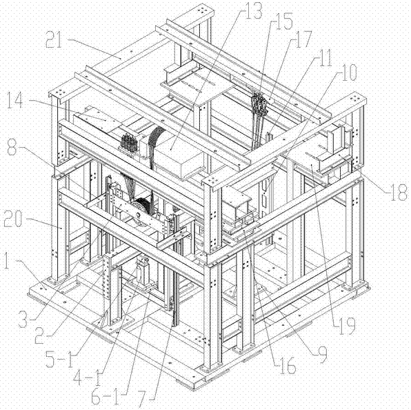
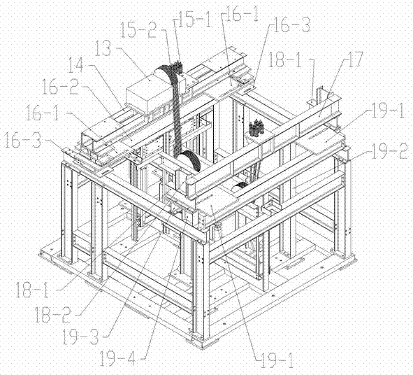
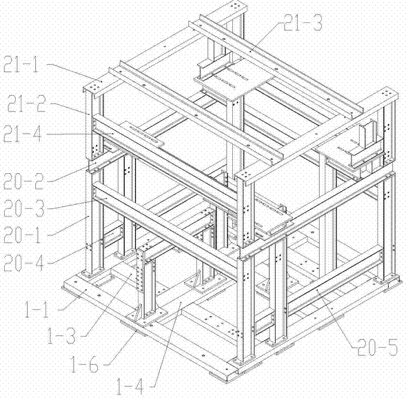
[0041] Such as figure 1 , Figure 4 and Figure 5 As shown, the elevator strength test device of the present invention includes: a base 1, a counterweight gantry 2 located on the left side of the base 1, and a car frame gantry 9 located at the middle of the base 1. The lower end of the heavy gantry frame 2 is fixed to the base 1 by bolts or welding, and the car frame gantry 9 is fixed to the base 1 by bolts or welding.

[0042] Such as image 3 As shown, the base 1 is welded into a horizontal four-frame by four base channel steel 1-1 with the notch facing downwards, and the interior of the four-frame is composed of at least one (preferably two) installation channel steel 1-1 with the notch facing downward. 4. Weld at least six support channel steels 1-3 to form a base support structure flush with the four frames; there are at least eight backing plates 1-6...


PUM


Abstract

The invention provides a lift strength tester, which comprises a base, a counterweight gantry, a car frame gantry, a simplified counterweight housing, a simplified car frame, a main engine and a wire rope are arranged on the base, main guide rails are arranged on both sides of the gantry direction of the car frame gantry, the simplified car frame is perpendicularly fastened with the car frame gantry, and can slide up and down along the main guide rails, auxiliary guide rails are arranged on both sides of the gantry direction of the counterweight gantry, the simplified counterweight housing is perpendicularly fastened with the counterweight gantry, and can slide up and down along the auxiliary guide rails, a second jack is arranged between a lower car frame crossbeam and a horizontal support frame of the car frame gantry, a first jack is arranged between a lower counterweight crossbeam and a horizontal support frame of the counterweight gantry, both ends of the wire rope is hung, and the wire rope sequentially rounds a counterweight diverting pulley, a main engine traction pulley and a car frame diverting pulley. The lift strength tester adopts the jacks to replace the original weight and the complex hydraulic system as power sources, and is simpler and more convenient in terms of carrying, installation, operation and maintenance.

Description

【Technical field】 [0001] The invention relates to a strength test device, in particular to a strength test device for testing a vertical elevator main engine, a main engine beam, a car side rope head beam, a counterweight upper beam and a car frame upper beam. 【Background technique】 [0002] The vertical elevator strength test device is a device used to analyze the strength of newly designed elevator main engine, main engine beam, elevator rope head beam, counterweight upper beam, car frame upper beam and other components when developing new elevator types. These previous devices often only perform strength tests on a certain component, and use heavy blocks or complex hydraulic cylinders to load. [0003] In the past, when analyzing the strength of the counterweight frame, it was necessary to build a gantry frame with a height of 4 to 5 meters. A manual hoist was hung on the gantry frame. The manual hoist was connected to the upper beam of the counterweight frame. During the...

Claims


Application Information

Patent Timeline
Patent Type & Authority Patents(China)
IPC IPC(8): B66B5/00
Inventor 邹金灿黄宗耀潘浩赵明伟唐电波
Owner HITACHI ELEVATOR CHINA
Why Eureka
Try Eureka