
Annealing furnace material rack

A technology for annealing furnaces and material racks, which is applied in the direction of furnaces, furnace components, lighting and heating equipment, etc., which can solve the problems of small furnace loading capacity, large annealing energy consumption, and low annealing efficiency, and achieve the effect of improving production efficiency

Inactive Publication Date: 2012-10-24
郭丰亮
View PDF3 Cites 0 Cited by
  • Summary
  • Abstract
  • Description
  • Claims
  • Application Information

AI Technical Summary

Problems solved by technology

[0003] The technical problem mainly solved by the present invention is to provide an annealing furnace material rack, which can solve the problems of the existing material rack such as small amount of furnace loading, low annealing efficiency, and large annealing energy consumption.

Method used


Image

  • Annealing furnace material rack

Examples


Embodiment Construction

[0009] The preferred embodiments of the present invention will be described in detail below in conjunction with the accompanying drawings, so that the advantages and features of the present invention can be more easily understood by those skilled in the art, so as to define the protection scope of the present invention more clearly.

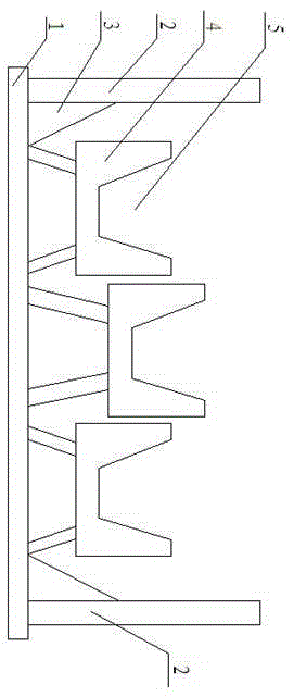
[0010] see figure 1 , the embodiment of the present invention includes: a base 1, a fixed rod 2 and a plurality of brackets 4, the bracket 4 is fixed on the base 1, the fixed rods 2 are arranged on both sides of the base 1, and each bracket is provided with a V-shaped groove 5 at a longitudinal position, The plurality of brackets 4 are in a staggered structure, which increases the loading space of the material rack and better fixes the material.

[0011] Further, a reinforcing rib 3 is provided between the fixed rod 2 and the bracket 4, so that the fixed rod 2 and the bracket 4 are better fixed.

[0012] Different from the prior art, the present...


PUM


Abstract

The invention discloses an annealing furnace material rack, which includes: a base, fixed rods and a plurality of supports. The supports are fixed on the base, and the fixed rods are arranged on two sides of the base. Each support is provided with a V-shaped groove in a longitudinal position, and the plurality of supports are arranged in a high-low staggered structure. By means of the above way, the annealing furnace material rack disclosed in the invention can solve the problems of small furnace charging capacity, low annealing efficiency, large annealing energy consumption and the like in existing material racks, and has the advantages of large charging capacity, production efficiency improving, energy saving and consumption reduction, etc.

Description

technical field [0001] The invention relates to the technical field of annealing devices, in particular to an annealing furnace charge rack with large furnace loading capacity, high production efficiency, energy saving and consumption reduction. Background technique [0002] The annealing furnace is the main equipment produced by the factory, and it is also the focus of energy consumption. There is only one annealing rack on each furnace of the existing annealing furnace, and multiple storage positions are set on the rack. However, in the actual operation process, due to the influence of the weight of the material, the actual loading amount of the rack is quite different from the expected one. The efficiency is low, and the energy consumption of annealing is large. Contents of the invention [0003] The technical problem mainly solved by the present invention is to provide a material rack for annealing furnace, which can solve the problems of small charging capacity, ...

Claims


Application Information

Patent Timeline
IPC IPC(8): C21D1/26F27D5/00
Inventor 郭丰亮
Owner 郭丰亮
Learn More