

Vertical seam type fishway structure
A technology of vertical slits and fish passages, which is applied in water conservancy projects, marine engineering, coastline protection, etc., can solve problems such as large impact, unfavorable river ecological protection, and reduce water flow velocity, so as to avoid large water flow velocity and be beneficial to ecological protection. , Improve the effect of energy dissipation
- Summary
- Abstract
- Description
- Claims
- Application Information
AI Technical Summary
Problems solved by technology
Method used
Image

Examples
Embodiment
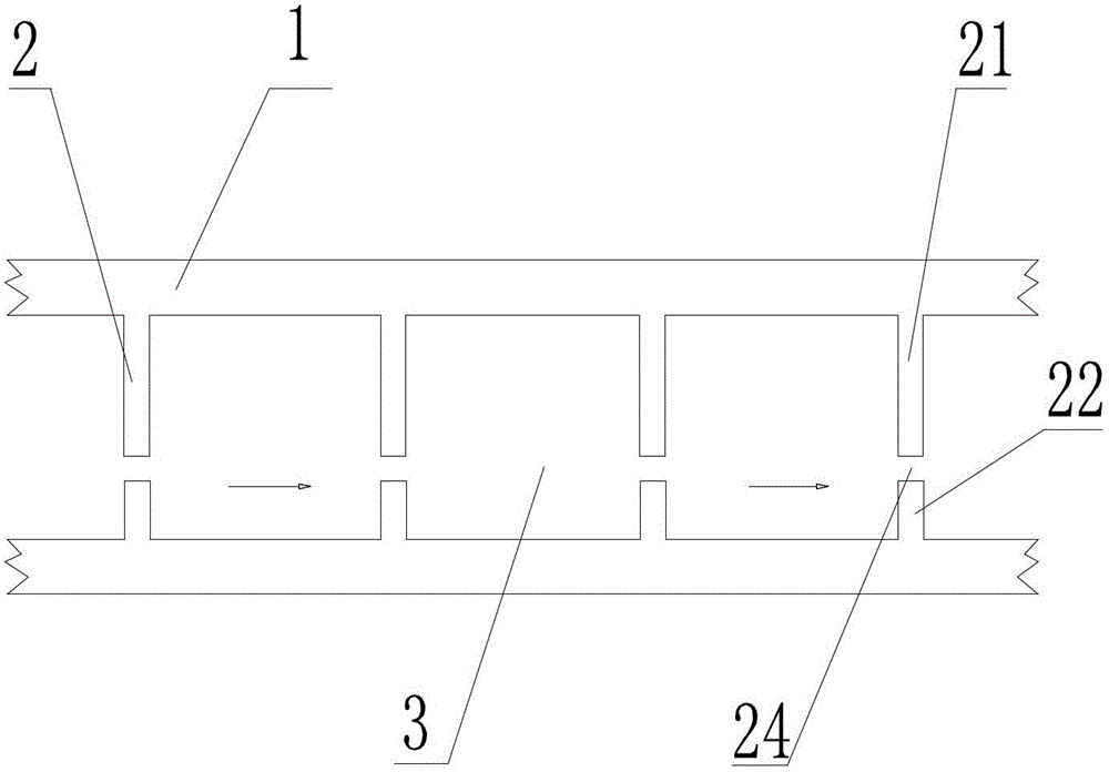
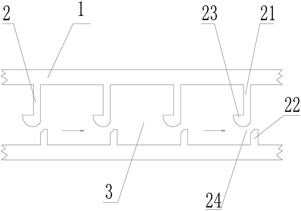
[0024] Choose three pond chamber vertical seams 24 on the vertical seam type fishway structure described in the present invention and detect the water flow velocity at respective pond chamber vertical seam 24 places, also choose three pond chamber vertical seam 24 places on the prior art vertical seam type fishway structure Pool chamber vertical seam 24 and detect the water flow velocity at respective pool chamber vertical seam 24 places, and three pond chamber vertical seams 24 that the present invention chooses and the three pond chamber vertical seams 24 that prior art chooses are in the position in respective fishway Identical, and numbered as 1#, 2#, 3# in pairs, promptly be positioned at the pool chamber vertical seam 24 numbering identical in the same position.
[0025] The following table is a comparison table of the water flow velocity at 24 vertical seams of the tank chamber between the vertical seam fishway structure of the present invention and the vertical seam fis...
PUM
 Abstract
Description
Claims
Application Information