Special-shaped step energy dissipater

A technology of energy dissipators and steps, applied in water conservancy engineering, marine engineering, coastline protection and other directions, can solve the problem that the rectangular stepped spillway cannot meet the requirements of engineering operation, and achieves the avoidance of cavitation erosion, strong turbulence, and simple structure. Effect

Inactive Publication Date: 2017-02-22
SICHUAN UNIV
View PDF3 Cites 6 Cited by
  • Summary
  • Abstract
  • Description
  • Claims
  • Application Information

AI Technical Summary

Problems solved by technology

The traditional rectangular step spillway can no longer meet the actual operation requirements of the project, so it is necessary to improve the layout of the traditional step shape or design a new step shape

Method used


Image

  • Special-shaped step energy dissipater
  • Special-shaped step energy dissipater
  • Special-shaped step energy dissipater

Examples


Embodiment 1

[0051] What is the relationship between the slope of the floor and the angle of the inclined wall in the examples and the numerical values ​​defined in the claims? All are within the scope defined by the claims.

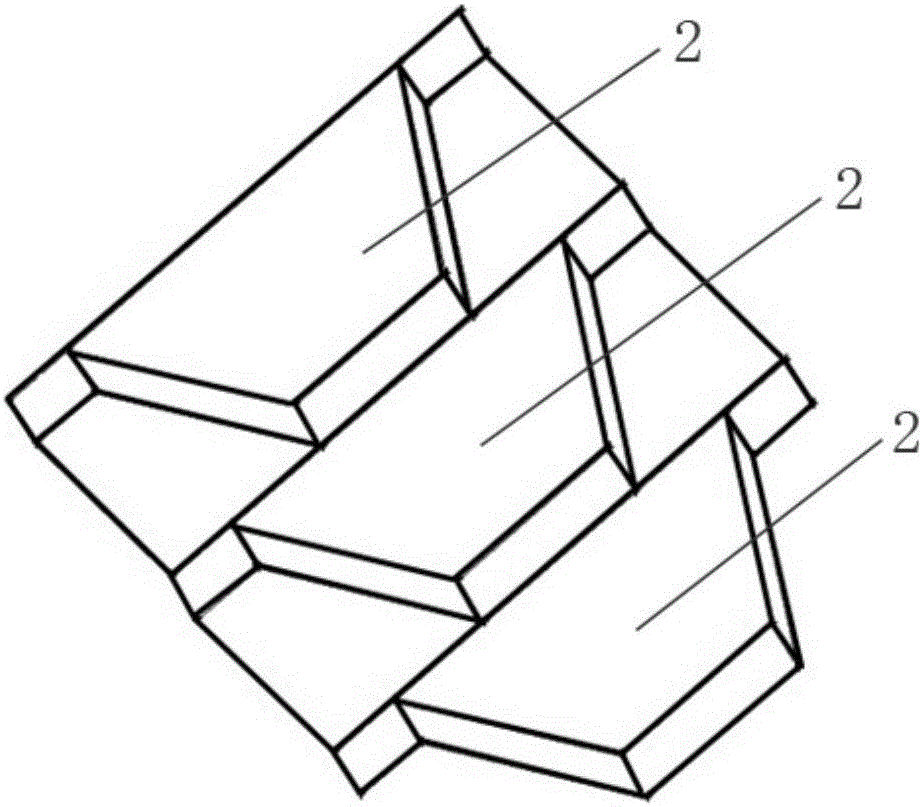
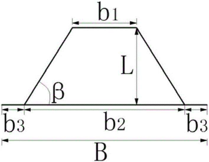
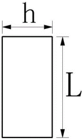
[0052] In this embodiment, the trapezoidal step energy dissipator is used for the spillway, as figure 1 , 2 , 3, 4 and 17, the maximum single-width discharge of the spillway is q=240m 3 / s.m, spillway width B=30m, floor slope θ=18°. The width of the trapezoidal step 2 set on the bottom plate of the spillway is B=30m at the end and b at the head 1 =10m, tail width b 2 = 30m, the distance between the tail of the trapezoidal step 2 and the side wall 1 of the spillway or spillway is b 3 =0m; the length of the step 2 is L=12m, the angle of the inclined wall of the trapezoidal step 2 is β=50°; the height of the trapezoidal step 2 is h=4m, and a total of 30 steps are set with a drop of 120m.

[0053] Model tests show that the flow velocity at the beginning section of ...

Embodiment 2

[0055] In this embodiment, the triangular step energy dissipator is used for the spillway, such as Figure 5 , 6 , 7, 8 and 18, the maximum single-width discharge of the spillway is q=160m 3 / s.m, spillway width B=25m, floor slope θ=27°. Width b at the end of the triangular step 3 set on the bottom plate of the spillway 2 = 15m, the distance from the tail of the triangular step 3 to the spillway or the inner side wall 1 of the spillway is b 3 = 5m; the length of the step 3 is L=12m, the angle of the inclined wall of the triangular step 3 is β=58°; the height of the step 2 is h=6m, and a total of 20 steps are set with a drop of 120m.

[0056] The model test shows that the flow velocity at the beginning section of the triangular-step spillway in this embodiment is 25m / s, the flow velocity at the end section of the step is 27m / s, and the energy dissipation rate is about 75.5%. The water flow in the spillway flows from the third step Begin to aerate strongly, the water after t...

Embodiment 3

[0058] In this embodiment, the dovetail-shaped step energy dissipator is used for the spillway, such as Figure 9 , 10 , 11, 12 and 19, the maximum single-width discharge of the spillway is q=200m 3 / s.m, spillway width B=25m, floor slope θ=22°. Width b at the end of the dovetail step 4 set on the bottom plate of the spillway 2 =20m, the middle width of the dovetail is b 4 = 5m; the length L of the dovetail-shaped steps 4 = 10m, the angle of the inclined wall of the dovetail-shaped steps 4 β = 45°; the height of the dovetail-shaped steps 4 h = 4m, a total of 25 steps are set, and the drop is 100m.

[0059] The model test shows that the flow velocity at the beginning section of the dovetail-shaped spillway in this embodiment is 20m / s, the flow velocity at the end section of the step is 25m / s, and the energy dissipation rate is about 73.5%. The steps begin to be strongly aerated, and the water flow after the second step is full of air bubbles, presenting a "white water" stat...


PUM


Abstract

The invention discloses a special-shaped step energy dissipater and belongs to the field of flood discharge and energy dissipation facilities in the water conservancy and hydropower engineering. The special-shaped step energy dissipater comprises steps in different stair shapes, and the steps in different stair shapes are formed by stacking a plurality of trapezoidal steps, triangular steps, dovetail-shaped steps and tongue-shaped steps, wherein the vertical faces of each step are multi-surfaces or curved surfaces. The energy dissipater is applicable to stair energy dissipation of a low-Froude-number and large discharge per unit width spillway or flood discharging tunnel, the energy dissipation rate is effectively increased, and the cavitation and cavitation erosion risk is reduced; and water flow of a traditional rectangular step energy dissipater is two-dimensional flow, water flow of the special-shaped step energy dissipater is three-dimensional flow, the vortex on the special-shaped steps has various dimensions and is a three-dimensional vortex, the water flow turbulence is strong, and therefore the energy dissipation effect is superior to that of a rectangular step spillway or flood discharging tunnel under the same condition. The special-shaped step energy dissipater can serve as a main energy dissipater in flood discharge and energy dissipation of the low-Froude-number and large discharge per unit width spillway or flood discharging tunnel.

Description

technical field [0001] The invention belongs to the field of energy dissipation facilities in water conservancy and hydropower projects, in particular to a special-shaped step energy dissipation facility used in a spillway with a low Floyd's number and a large single-width flow rate or a spillway. Background technique [0002] Stepped spillways have become a popular method of safe flood discharge over the past few decades. Due to the cumulative energy dissipation of the steps, the energy dissipation rate is improved, the disadvantages of centralized energy dissipation are avoided, and the operation of energy dissipation buildings is safer. Relevant research data show that: under the same slope and different single-width discharge conditions, the energy dissipation rate of the stepped overflow dam generally accounts for 48% to 71% of the total energy, while the energy dissipation rate of the chute section of the smooth overflow dam under the same conditions It only accounts ...

Claims


Application Information

Patent Timeline
Patent Type & Authority Applications(China)
IPC IPC(8): E02B8/06
CPCE02B8/06
Inventor 王磊刁明军薛宏程孙浩淼
Owner SICHUAN UNIV
Why Eureka
Try Eureka