Chemical waste treatment device and treatment process

A technology of waste treatment and treatment process, which is applied in the chemical industry, hydrocarbon oil treatment, petroleum industry, etc. It can solve the problem of simultaneous treatment of waste oil, waste gas, and solid chemical waste, the inability to completely remove organic matter from chemical waste gas, and the complex composition of chemical waste gas and other problems, to achieve the effect of reducing side reaction products, reducing exhaust gas concentration, and strong adsorption capacity

Active Publication Date: 2016-12-14
山东天景工程设计有限公司 +1
View PDF7 Cites 3 Cited by
  • Summary
  • Abstract
  • Description
  • Claims
  • Application Information

AI Technical Summary

Problems solved by technology

The catalytic reaction method is mainly used for the purification of high-temperature, high-concentration, and continuous emission of organic waste gas. However, due to the complex composition of chemical waste gas, the organic matter in chemical waste gas cannot be completely removed by catalytic reaction methods.
The direct catalytic reaction method is suitable for the

Method used


Image

  • Chemical waste treatment device and treatment process
  • Chemical waste treatment device and treatment process
  • Chemical waste treatment device and treatment process

Examples


Embodiment 1

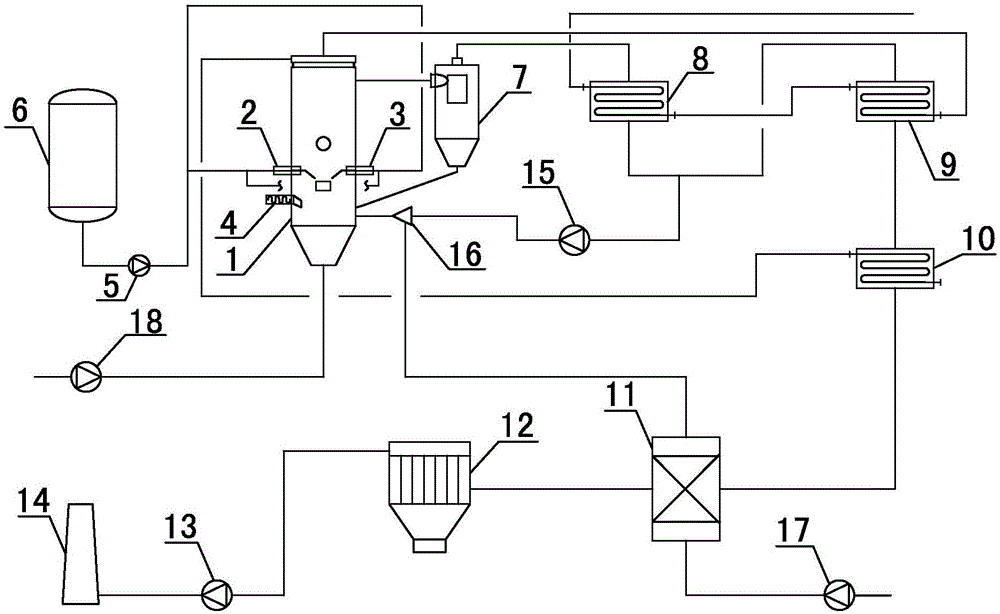
[0067] like figure 1 As shown, the chemical waste treatment device of the present invention includes a reactor 1, and the side of the reactor 1 is provided with a first material gun 2, a second material gun 3 and a solid material conveyor 4, a first material gun 2, a waste oil transfer pump 5 is connected to the waste oil storage tank 6 in turn, the second material gun 3 is connected to the waste oil delivery pump 5, the reactor 1, the cyclone separator 7, the front heat exchanger 8, the rear heat exchanger 9, the energy-saving heat exchanger 10, The air preheater 11, the dust collector 12, and the exhaust fan 13 are connected to the chimney 14 in sequence; Connected in sequence, the flue gas mixer 16 is connected to the air preheater 11 , the energy-saving heat exchanger 10 is connected to the reactor 1 , the secondary fan 17 is connected to the air preheater 11 , and the primary fan 18 is connected to the reactor 1 .

[0068] When the device is running, the waste oil is sen...

Embodiment 2

[0091] The chemical waste treatment device is the same as that in Example 1.

[0092] Adopt the processing technology of the above-mentioned chemical waste treatment device, and the steps are as follows:

[0093] (1) The reactor of the device is Φ1000mm diameter specification; 300kg of catalyst and 60kg of desulfurizer are put into the reactor for the first time;

[0094] (2) The waste gas is fed into the jacket of the first material gun and the second material gun of the reactor, the reaction is started, and the waste gas is adjusted to 350Nm 3 / h;

[0095] (3) Start the primary fan, adjust the frequency conversion, and provide an air volume of 4000m 3 / h;

[0096] (4) the temperature in the reactor is increased, and the temperature reaches 400 °C;

[0097] (5) The waste oil is sent to the waste oil storage tank from the outside, heated to 100 ℃ with steam, pressurized by the waste oil pump to 0.5MPa, and sent into the waste oil into the nozzles of the first and second fe...

Embodiment 3

[0109] The chemical waste treatment device is the same as that in Example 1.

[0110] Adopt the processing technology of the above-mentioned chemical waste treatment device, and the steps are as follows:

[0111] (1) The device reactor is Φ900mm diameter specification; 200kg of catalyst and 40kg of desulfurizer are put into the reactor for the first time;

[0112] (2) The waste gas is fed into the jacket of the first material gun and the second material gun of the reactor, the reaction is started, and the waste gas is adjusted to 200Nm 3 / h;

[0113] (3) Start the primary fan, adjust the frequency conversion, and provide an air volume of 3000m 3 / h;

[0114] (4) the temperature in the reactor is increased, and the temperature reaches 400 °C;

[0115] (5) The waste oil is sent to the waste oil storage tank from the outside, heated to 120 ℃ with steam, pressurized by the waste oil pump to 0.6MPa, and sent into the waste oil into the nozzles of the first and second feed guns ...


PUM


Abstract

The invention belongs to the technical field of chemical waste treatment, and particularly relates to a chemical waste treatment device and treatment process. The chemical waste treatment device comprises a reactor, wherein a first material gun, a second material gun and a solid material conveyor are arranged at the side part of the reactor; the reactor, a cyclone separator, a front heat exchanger, a rear heat exchanger, an energy-saving heat exchanger, an air preheater, a dust collector, an exhaust fan and a chimney are connected in sequence; a high-temperature fan is connected with the front heat exchanger and the rear heat exchanger; the high-temperature fan, a flue gas mixer and the reactor are connected in sequence; the flue gas mixer is connected with the air preheater; the energy-saving heat exchanger is connected with the reactor; a secondary fan is connected with the air preheater; and a primary fan is connected with the reactor. According to the chemical waste treatment device and treatment process, waste oil, waste gas and solid chemical waste enter into the reactor at the same time for treatment. The waste gas can serve as a preheating energy source, but heavy oil and natural gas do not need to serve as preheating energy sources, so that the cost is relatively low.

Description

technical field [0001] The invention belongs to the technical field of chemical waste treatment, and in particular relates to a chemical waste treatment device and a treatment process. Background technique [0002] In the production process of chemical industry and other industries, a large amount of waste oil, waste gas and solid chemical waste will be produced, which are harmful to human body and cause great damage to the environment. At present, the main method of treating waste oil is to make secondary use of waste oil refining, or obtain gasoline, diesel oil, etc. as fuel, but this method is expensive and cannot be promoted; domestic waste oil is also directly burned as fuel, but the The reaction of the equipment is insufficient, the heat utilization rate is low, and a lot of toxic gases such as sulfur dioxide and carbon monoxide are produced after the reaction. These toxic gases are directly discharged without purification treatment, causing environmental pollution. T...

Claims


Application Information

Patent Timeline
IPC IPC(8): B01D53/86B01D53/50C10G29/00B09B3/00B09B5/00
CPCB01D53/8609B09B3/00B09B5/00C10G29/00C10G2300/70Y02P20/10
Inventor 董树富杨永杜灵王续宝
Owner 山东天景工程设计有限公司
Why Eureka
Try Eureka