Eddy-current vertical-well energy dissipation structure of water discharging hole for ditchwater treatment and water discharging method

A technology for ditch water treatment and whirlpool shafts, applied in water conservancy projects, marine engineering, coastline protection, etc., can solve problems such as hidden safety hazards, long tunnel lines, and large amount of water outlet protection works, so as to facilitate construction and save engineering investment. Good effect, energy dissipation effect

Active Publication Date: 2016-11-09
POWERCHINA CHENGDU ENG
View PDF4 Cites 4 Cited by
  • Summary
  • Abstract
  • Description
  • Claims
  • Application Information

AI Technical Summary

Problems solved by technology

According to the operation of the implemented project, the construction of the drainage tunnel adopting the above layout scheme is relatively difficult, the tunnel line is long, the amount of water outlet protection work is large, the energy dissipation effect of the water outlet is no

Method used


Image

  • Eddy-current vertical-well energy dissipation structure of water discharging hole for ditchwater treatment and water discharging method
  • Eddy-current vertical-well energy dissipation structure of water discharging hole for ditchwater treatment and water discharging method
  • Eddy-current vertical-well energy dissipation structure of water discharging hole for ditchwater treatment and water discharging method

Examples


Example Embodiment

[0025] The present invention will be further described below in conjunction with the drawings, in which the direction of the arrow in the figure is the direction of water flow.

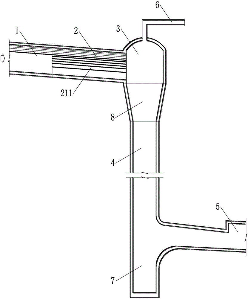
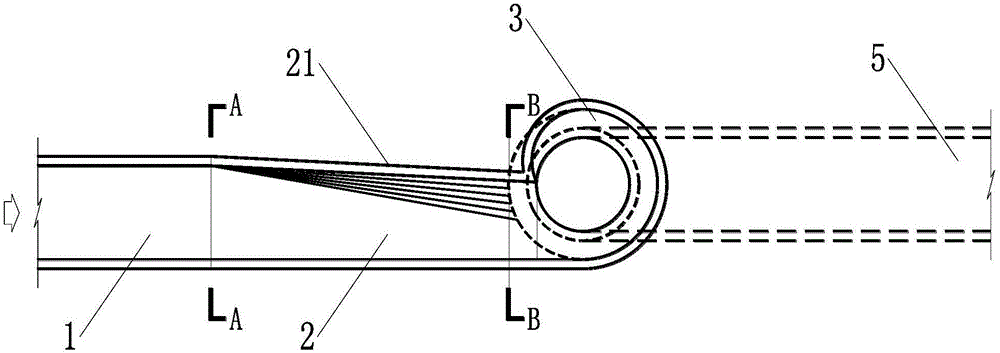
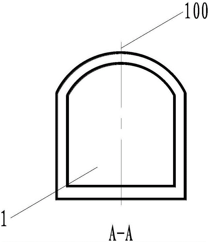
[0026] Such as Figure 1 to Figure 5 As shown, the drainage tunnel vortex shaft energy dissipation structure for ditch water treatment of the present invention includes a high drainage hole 1, a side contraction hole 2, a vortex chamber 3, a shaft 4, a low drainage hole 5, and a vent 6, so The side contraction hole 2 is arranged between the high drainage hole 1 and the swirling vortex chamber 3, the top end of the shaft 4 is in communication with the swirling vortex chamber 3, and the bottom end of the shaft 4 is in communication with the low drainage hole 5. The vent 6 is arranged at the top of the swirling vortex chamber 3, the side shrinking hole 2 has an inclined shrinking side wall 21, the inclined shrinking side wall 21 is arranged obliquely, and the distance between the bottom of the inclined shri...


PUM


Abstract

The invention discloses an engineering construction of a hydropower station, and particularly discloses an eddy-current vertical-well energy dissipation structure of a water discharging hole for ditchwater treatment. The invention provides the eddy-current vertical-well energy dissipation structure of the water discharging hole for the ditchwater treatment, which can be used for removing the disadvantage that a water discharging hole which reaches a bottom through one slope is arranged in an alpine gorge region, and further can generate eddy-current energy dissipation, for all different coming flow rates, in a vertical well. The eddy-current vertical-well energy dissipation structure of the water discharging hole for the ditchwater treatment comprises a high water discharging hole, a side shrinking hole, an eddy-current volute chamber, a vertical well, a low water discharging hole and a vent hole, wherein the side shrinking hole is arranged between the high water discharging hole and the eddy-current volute chamber; the top end of the vertical well communicates with the eddy-current volute chamber; the bottom end of the vertical well communicates with the low water discharging hole; the vent hole is arranged at the top part of the eddy-current volute chamber; the side shrinking hole is provided with one oblique shrinking side wall; and the oblique shrinking side wall is arranged obliquely. After entering the side shrinking hole, water currents of different flow rates are shrunk laterally; the coming flow rates of different water heads and different flow rates can be guaranteed to all have eddying initial flow velocities after entering the eddy-current volute chamber; and the water currents can be better subjected to energy dissipation in a subsequent process.

Description

technical field [0001] The invention relates to an engineering structure of a hydropower station, in particular to a drainage hole swirl shaft energy dissipation structure for ditch water treatment under the condition of discharging different incoming and outgoing flows in tributary valleys in alpine and canyon areas. In addition, the present invention also relates to a drainage method, especially a drainage method for tributary valleys in alpine and canyon regions. Background technique [0002] When constructing water conservancy and hydropower projects in high mountain and valley areas, due to the small number of construction sites available in the project area, a large amount of spoils need to be stockpiled in the project construction, and various construction factories and other temporary construction facilities need to be arranged. Therefore, it is often used The tributary valleys near the project area are used as spoil grounds and construction sites. The tributary vall...

Claims


Application Information

Patent Timeline
IPC IPC(8): E02B8/06
CPCE02B8/06
Inventor 王永刚相昆山易文明孔科汤雷
Owner POWERCHINA CHENGDU ENG
Why Eureka
Try Eureka