
Built-in driven pneumatic valve

A pneumatic valve, driven technology, applied to pneumatic valves. It can solve the problems of short service life, inconvenient installation and debugging, and large volume of the valve, and achieve the effect of no relative friction, compact structure and long service life.

Inactive Publication Date: 2012-10-24
江苏东源阀门检测技术有限公司
View PDF3 Cites 0 Cited by
  • Summary
  • Abstract
  • Description
  • Claims
  • Application Information

AI Technical Summary

Problems solved by technology

[0003] In order to overcome the disadvantages of the existing various types of pneumatic valves with external pneumatic devices, which are large in size, heavy in structure, inconvenient to install and debug, and due to the relative friction between the valve seat and the sealing ring, the short service life of the valve, the present invention provides a Built-in actuated pneumatic valve

Method used


Image

  • Built-in driven pneumatic valve

Examples


Embodiment Construction

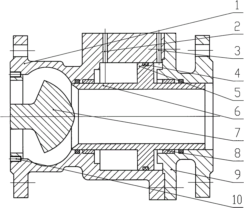
[0010] Such as figure 1 As shown, a built-in driven pneumatic valve includes a valve body 1, a valve cover 9, and a valve disc 7. The valve disc 7 is fixed in the valve body 1 by screws 10, and the valve cover 9 and the valve body 1 are connected by fasteners. There is also a hollow valve core 6 installed in the valve body 1, the front end of the valve core 6 forms a sealing pair with the sealing surface of the valve disc 7, and there is a boss 5 in the middle of the valve core 6, and the boss 5 and the valve body 1 pass through an O-ring 4 sealing, between the front end of the valve core 6 and the valve body 1 and between the rear end of the valve core 6 and the valve cover 9 are sealed by an O-ring 4 , and the valve body 1 at the front end of the boss 5 of the valve core 6 is provided with a valve opening inlet The air port 2 is opened on the valve body 1 of the boss 5 of the valve core 6 to open the valve air inlet 3 . Between the front end of the valve core 6 and the valv...


PUM


Abstract

The invention provides a built-in driven pneumatic valve which comprises a valve body, a valve bonnet and a valve clack, wherein the valve clack is fixed in the valve body through screws, the valve bonnet and the valve body are connected through a fastener, a hollow valve core is arranged in the valve body, the front end part of the valve core and the sealing surface of the valve clack are formed into a seal pair, the middle part of the valve core is provided with a boss, the boss and the valve body are sealed through an O-shaped seal ring, the front end of the valve core and the valve body, as well as the rear end of the valve core and the valve bonnet, are respectively sealed through an O-shaped seal ring, the valve body at the front end of the boss of the valve core is provided with a valve-opened air inlet, the valve body on the boss of the valve core is provided with a valve-closed air inlet, and a guide sleeve is also respectively arranged between the front end of the valve core and the valve body and between the rear end of the valve core and the valve bonnet. The built-in driven pneumatic valve disclosed by the invention has the advantages that: as a driving device is arranged in an inner cavity of the valve body, the pneumatic valve is compact in structure; and in the processes of opening and closing, the seal pair makes a translational motion, and no relative friction exists, therefore, the service life of the pneumatic valve is long.

Description

technical field [0001] The invention relates to a valve device, in particular to a pneumatic valve. Background technique [0002] At present, all kinds of pneumatic valves used in the fields of metallurgy, petrochemical, and nuclear power are generally composed of pneumatic devices outside the valve body, which are large in size, heavy in structure, and inconvenient to install and debug. Due to the relative friction between them, the service life of the valve is short. Contents of the invention [0003] In order to overcome the disadvantages of the existing various types of pneumatic valves with external pneumatic devices, which are large in size, heavy in structure, inconvenient to install and debug, and due to the relative friction between the valve seat and the sealing ring, the short service life of the valve, the present invention provides a Built-in actuated pneumatic valve. [0004] The technical solution adopted by the present invention to solve the technical pro...

Claims


Application Information

Patent Timeline
Patent Type & Authority Applications(China)
IPC IPC(8): F16K1/00F16K1/36F16K31/12
Inventor 张逸芳陆平
Owner 江苏东源阀门检测技术有限公司
Learn More