
Fixed support device and operating method thereof

A technology for fixing brackets and fixing foundations. It is applied in the direction of pipeline brackets, pipes/pipe joints/fittings, mechanical equipment, etc. It can solve problems such as high labor intensity, inconvenient installation, and troublesome replacement, so as to reduce on-site workload and avoid replacement. Troublesome, easy to install and operate

Active Publication Date: 2014-09-17
上海和蕴机电科技有限公司
View PDF5 Cites 0 Cited by
  • Summary
  • Abstract
  • Description
  • Claims
  • Application Information

AI Technical Summary

Problems solved by technology

[0011] 1. Each type of fixing bracket device can only correspond to a basic component of one shape and corresponding size specification. The fixing bracket device cannot be used for common fixing bracket devices between basic components of different shapes or sizes. improve
[0012] 2. It needs to be operated by both hands, which is inconvenient to install, and the safety hazard of the staff is great, and the labor intensity is high
[0013] 3. If the bracket is not suitable, it is troublesome to replace it, and there is a hidden danger of equipment and parts falling during the installation process
[0014] To sum up, it is necessary to solve the above-mentioned technical problems that are not conducive to on-site installation and operation, and develop a fixed bracket that has strong adaptability to on-site preset components, simple installation, and the bracket and accessories are not easy to fall during operation and has good safety performance. Device and method of operation thereof

Method used


Image

  • Fixed support device and operating method thereof
  • Fixed support device and operating method thereof
  • Fixed support device and operating method thereof

Examples


Embodiment 1

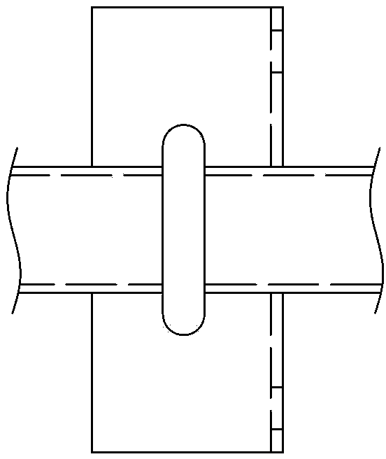
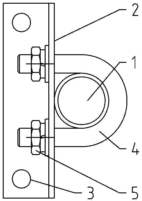
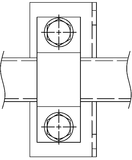
[0082] see Figure 7 to Figure 15 , a fixed bracket device, comprising: a bracket member 10, a hanging plate 9, a first bolt 22 and a bolt member 11, the bracket member 10 includes a bracket 12, and the bracket 12 is provided with two for connecting with field machines or parts The fixing hole 3 and two via holes 13 for connecting with the hanging board 9, the cross section of the hanging board 9 is "Z" shape, one end of which is connected with the bracket member 10 through the first bolt 22, and the other end is provided with a "U-shaped" opening 17, and the bracket member 10 and the hanging plate 9 form a cavity 18 with one side open. The bolt member 11 fixes the “U-shaped” open end of the hanging plate 9 to the bracket member 10 .

[0083] The fixed bracket device in this embodiment adopts a screw-fixed bracket component structure, which is suitable for installation conditions requiring a small adjustment margin. like Figure 11 , 12 As shown, this embodiment also inclu...

Embodiment 2

[0094] The structure and operation method of the fixing bracket device adopting the screw-fixed bracket component structure of the present invention have been introduced in detail above. Due to the high uncertainty in the field, sometimes a large adjustment margin is required. Therefore, the present invention can also adopt a threaded adjustable bracket structure to improve adaptability.

[0095] like Figure 16 to Figure 22 As shown, a fixed bracket device includes: a bracket member 10, a hanging plate 9, a first bolt 22 and a bolt member 11, the bracket member 10 includes a bracket 12, and the bracket 12 is provided with two The connecting fixing hole 3 and two through holes 13 for connecting with the hanging plate 9, wherein the through holes 13 for connecting with the bolt member 11 are elongated, and the cross-sectional area of ​​the bracket 12 is "U" shaped , to form the guide groove 25 of the sliding threaded plate 24. The cross-section of the hanging plate 9 is “Z”-s...

Embodiment 3

[0104] The structure and operation method of the fixing bracket device adopting the screw-fixed bracket component structure and the thread-adjustable bracket component structure of the present invention have been introduced in detail above. In addition, the present invention can also adopt a chute-type support member structure, and the positions of the first bolt and the bolt member can be adjusted arbitrarily in the chute, which has excellent adaptability.

[0105] like Figure 23 to Figure 29 As shown, a fixed support device includes: a support member 10, a hanging plate 9, a first bolt 22 and a bolt member 11, and the support member 10 is provided with two through chute 26, which are respectively used to connect with the field machine or zero Component connections, and connections to pegboards. The cross-section of the hanging plate 9 is “Z”-shaped, one end of which is connected to the support member 10 through the first bolt 22, and the other end is provided with a “U-sha...


PUM


Abstract

The invention relates to a fixed support device, which comprises a support component, wherein the support component is provided with multiple fixing holes or chutes connected with a machine or parts, the fixed support device further comprises a hanging plate, a first bolt and a bolt component, the section of the hanging plate is Z-shaped, one end of the hanging plate is connected with the support component through a first bolt, a U-shaped opening is arranged on the other end of the hanging plate, and a cavity provided with one opened size is encircled by the support component and the hanging plate; and the U-shaped opened end of the hanging plate and the support component are fixed by the bolt component. According to the invention, the operation is simple, the single-handed operation can be realized, and labor intensity is remarkably reduced; the fixed support device has good suitability for preset components at the site; and the beneficial effect of improving the working safety of workers can be realized in high-risk occasions, in particular work high above the ground. The fixed support device has the advantages of strong suitability, simple installation, low labor intensity and good safety performance.

Description

technical field [0001] The invention relates to the technical field of on-site installation operations, in particular to a fixing bracket device with strong adaptability, simple installation, low labor intensity and good safety performance and an operation method thereof. Background technique [0002] In daily production and life, there are a large number of installation operations that need to be carried out on site. At present, the commonly used operation method is: first install the fixed bracket device on the existing components on site, and then connect the machine or parts to the fixed bracket device. fixed. These installations are often characterized by poor operating conditions and unclear site foundations. However, the current common fixing brackets and installation methods do not fully consider these particularities, causing the fixing brackets to be modified or remade on the spot when the site conditions change slightly, and the installation is troublesome. [0...

Claims


Application Information

Patent Timeline
Patent Type & Authority Patents(China)
IPC IPC(8): F16L3/02
Inventor 韩敏贾国涛叶佳军孟辉李燕韩浩管超
Owner 上海和蕴机电科技有限公司
Learn More