Construction method of steel-concrete composite storey

A construction method and concrete layer technology, which is applied in the field preparation of formwork/formwork/work frame, building components, construction, etc., can solve the problems of slow construction speed and heavy on-site workload, and achieve fast construction speed and on-site Small workload, simple and reliable connection method

Inactive Publication Date: 2004-10-06
滕勇
View PDF0 Cites 11 Cited by
  • Summary
  • Abstract
  • Description
  • Claims
  • Application Information

AI Technical Summary

Problems solved by technology

The disadvantage of this construction method is the large amount of on-site work, so the construction speed is slow

Method used


Image

  • Construction method of steel-concrete composite storey
  • Construction method of steel-concrete composite storey
  • Construction method of steel-concrete composite storey

Examples


Embodiment Construction

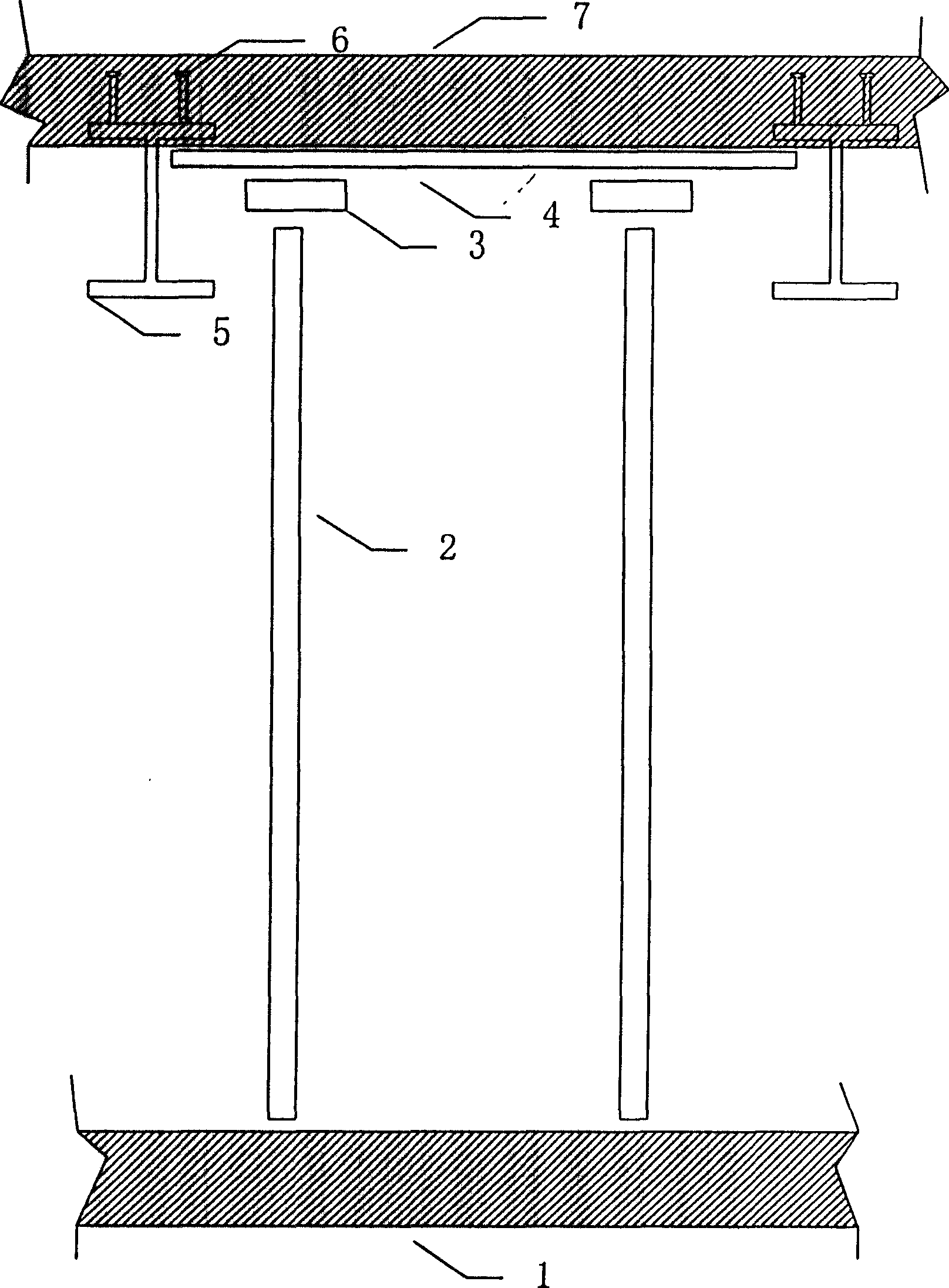
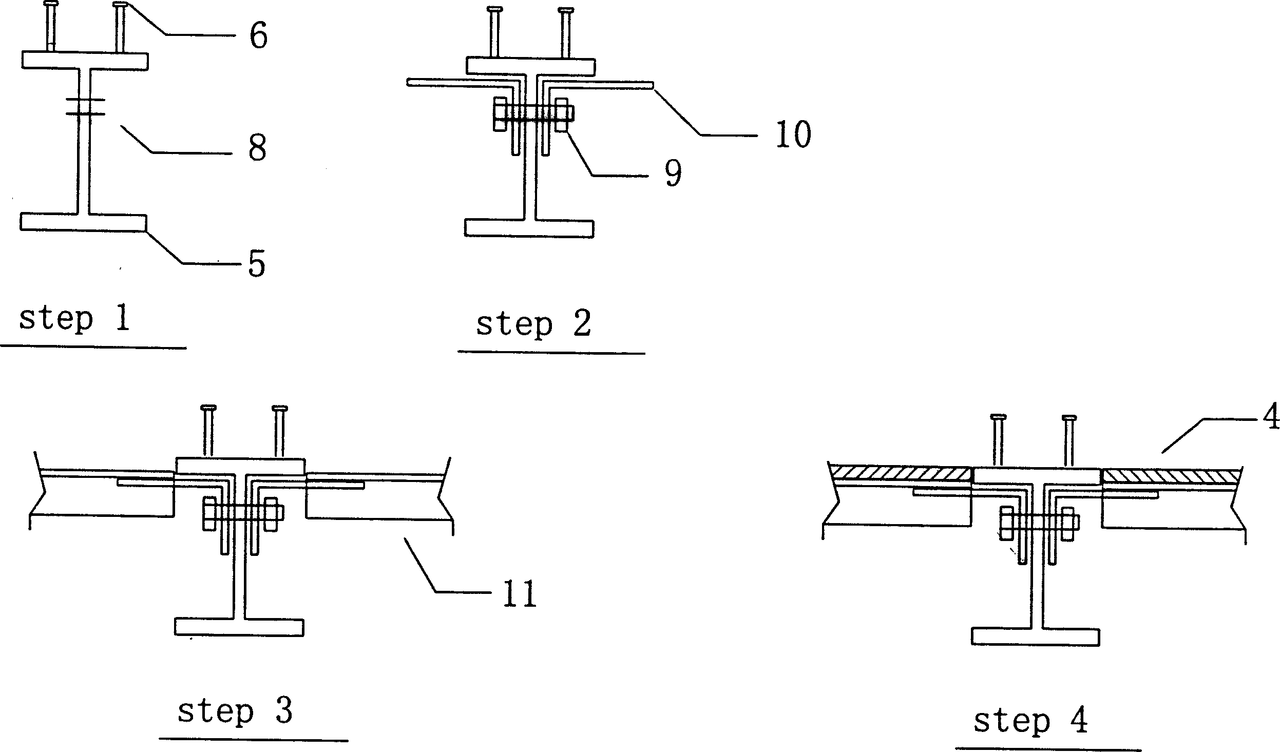
[0018] Such as figure 2 As shown, the method steps are:

[0019] (1) Pre-drilling connection holes 8 on the web of the steel beam 5;

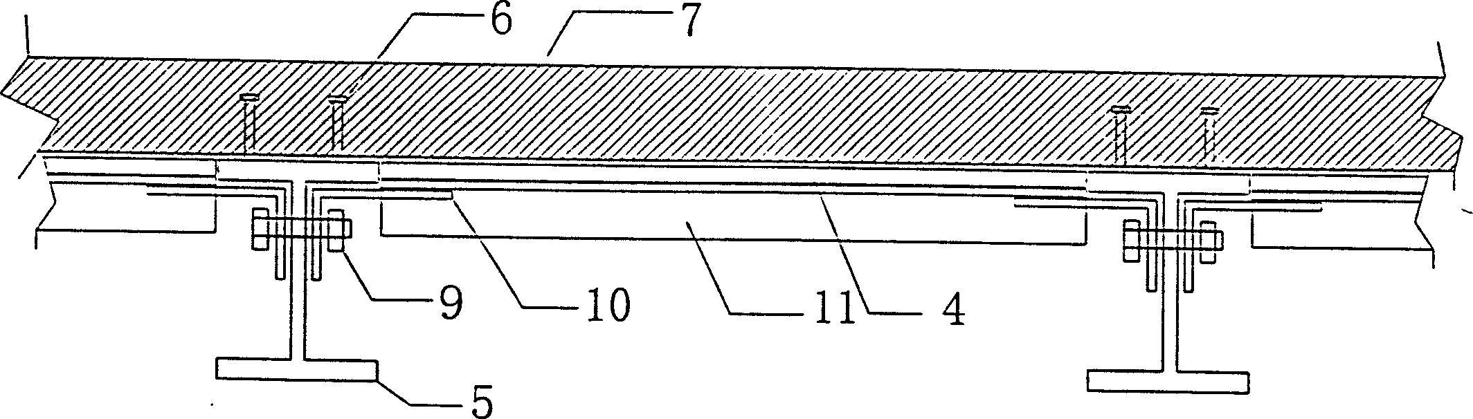
[0020] (2) The steel beam 5 is connected with the grooved angle steel bracket 10 through the connecting hole 8 of its web by the connecting piece 9 consisting of bolts and nuts;

[0021] (3) Insert T-shaped steel 11 between the angle steel brackets 10 as a cross brace;

[0022] (4) Lay a reusable formwork 4 on the T-shaped steel cross brace 11, and the formwork 4 adopts a standard composite plate of 1220 × 2400 × 15;

[0023] (5) tie steel bar and cast-in-place concrete layer on formwork 4;

[0024] (6) After the concrete reaches a certain strength, remove the connecting bolts 9, the angle steel brackets 10, the T-shaped joists 11 and the formwork 4 in sequence.


PUM


Abstract

A construction method for steel-concrete floor includes drilling on the web plate of steel beam, connecting the steel beam with brackets mode of angle steel, arranging T-shaped steel beams between brackets, spreading shutterings on the T-shaped steel beams, binding reinforcing bars, pouring concrete, solidifying, and detaching the brackets, T-shaped beam and shutterings. Its advantages are low cost and high construction speed.

Description

technical field [0001] The invention relates to a construction method of a steel-concrete combined floor in the construction field. Background technique [0002] The traditional construction methods for floor concrete of multi-storey or high-rise steel structure buildings are: figure 1 shown. Vertical braces 2 are erected from the ground or floor 1 below; horizontal braces 3 are supported on the vertical braces 2; formwork 4 is supported on the horizontal braces 3; reinforced concrete 7 is cast in place on the formwork 4. In the figure, 5 is a steel beam, and 6 is a shear key. The transmission line of the construction load is the formwork 4 , the cross brace 3 , the vertical brace 2 , the floor or the completed lower story 1 . The disadvantage of this construction method is that there is a large amount of on-site work, so the construction speed is slow. Contents of the invention [0003] The purpose of the present invention is to overcome the shortcomings of the existi...

Claims


Application Information

Patent Timeline
Patent Type & Authority Applications(China)
IPC IPC(8): E04G11/48
Inventor 滕勇
Owner 滕勇
Why Eureka
Try Eureka