Method for controlling a leak detector, and leak detector

A leak detector and energy supply technology, which is applied in the testing of machines/structural components, instruments, pump control, etc., and can solve problems such as inability to comply with waiting time, user miscalculation, etc.

Active Publication Date: 2012-10-24
普发真空公司
View PDF8 Cites 0 Cited by
  • Summary
  • Abstract
  • Description
  • Claims
  • Application Information

AI Technical Summary

Problems solved by technology

Other effects also lead to failure to observe these waiting times, for example when the user miscalculates the elapsed waiting time or if he forgets the manufacturer's recommendation

Method used


Image

  • Method for controlling a leak detector, and leak detector
  • Method for controlling a leak detector, and leak detector
  • Method for controlling a leak detector, and leak detector

Examples


Embodiment Construction

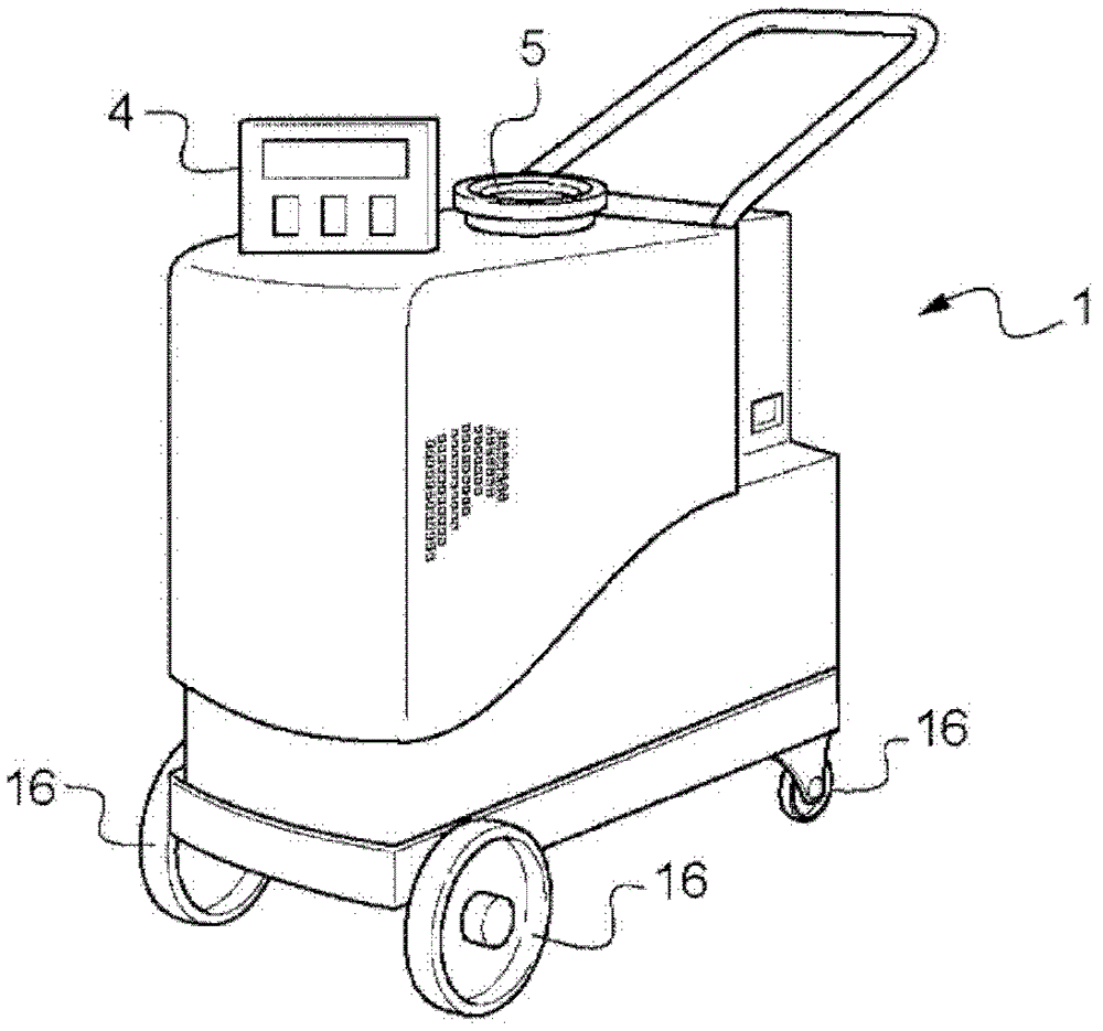
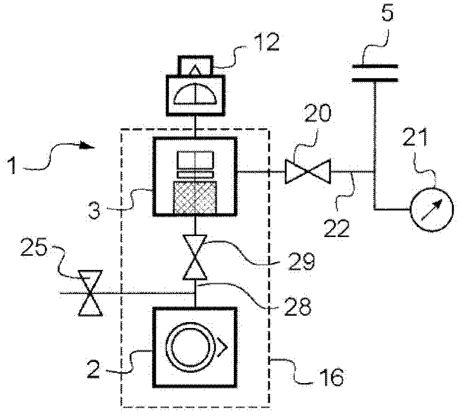
[0035] figure 1 and 2 An example of a leak detector 1 is depicted.

[0036] The leak detector 1 comprises a main vacuum pump 2, a secondary vacuum pump 3 connected to the main vacuum pump 2, a mass spectrometer 12 connected to the suction side of the secondary vacuum pump 3, and at least one notification device for notifying the user of the operating state of the leak detector 1 4.

[0037] The secondary vacuum pump 3 includes a rotor, a stator and a motor. The rotor is rotated by the motor in the stator when the motor is energized. figure 1 The gas inlet 5 of the leak detector 1 is shown.

[0038] The discharge side of the secondary vacuum pump 3 is connected to the suction side of the main vacuum pump 2 via a pumping pipe 28 provided with a first isolating solenoid valve 29 of the leak detector 1 .

[0039] According to another example not shown, the leak detector does not comprise a main vacuum pump: the outlet of the secondary vacuum pump 2 is designed to be connected...


PUM


Abstract

The invention relates to a method for monitoring a leak detector comprising: a secondary vacuum pump designed to be connected to a primary vacuum pump, the secondary vacuum pump comprising a motor, a rotor and a stator, the said rotor being capable of being rotated in the stator by the motor when the motor is powered, and at least one information means capable of being powered electrically, in order to inform a user of the operating state of the leak detector, characterized in that, in the event of the motor power supply being cut off, the kinetic energy of rotation of the secondary vacuum pump rotor in the form of electrical power (101) is recovered in order to power the information means (102). The invention also relates to a leak detector (1) using the said monitoring method.

Description

technical field [0001] The invention relates to a method for monitoring a leak detector comprising a secondary vacuum pump with a rotor, such as a turbomolecular, molecular or hybrid vacuum pump, and an associated leak detector. The invention applies more particularly to leak detectors that are movable on wheels or by means of a cart, such as portable leak detectors. Background technique [0002] In operation, the rotor of the secondary vacuum pump rotates at very high speeds, eg thousands of revolutions per minute, in order to create a high or ultra-high vacuum. Due to the extremely high speed of rotation and the inertia of the rotor, the user must wait a certain time after commanding the secondary vacuum pump to stop, for the rotor to stop effectively and to allow him to move the leak detector without risking damage to it. Specifically, hasty movements can cause the secondary vacuum pump to seize due to gyroscopic effects. Movement of the leak detector generates a thrust...

Claims


Application Information

Patent Timeline
Patent Type & Authority Applications(China)
IPC IPC(8): G01M3/02
CPCG01M3/205F04D27/008F04D19/042F04D27/0292
Inventor F·鲁韦尔D·皮埃尔让C·诺米内
Owner 普发真空公司
Why Eureka
Try Eureka