Supercharge Your Innovation With Domain-Expert AI Agents!

Electrophoretic display integrated with NFC (Near Field Communication) antenna

An electrophoretic display and electrophoretic display technology, applied in the direction of antenna, loop antenna, static indicator, etc., can solve the problems of easy wear and alignment of wiring, poor antenna signal quality, inaccuracy, etc.

Active Publication Date: 2012-10-24
TRULY IND LTD
View PDF7 Cites 8 Cited by
  • Summary
  • Abstract
  • Description
  • Claims
  • Application Information

AI Technical Summary

Problems solved by technology

[0005] In view of the unreasonable setting method of the NFC antenna of the electronic products equipped with the NFC antenna and electrophoretic display, the wiring is easy to wear or the alignment is not accurate, which leads to the problem of poor signal quality of the antenna
And it limits the range of options for the housing of electronic products. In the process of producing electrophoretic displays, it has the ability to integrate NFC antennas. It is necessary to design a new electrophoretic display integrated with NFC antennas to solve the above problems.

Method used


Image

  • Electrophoretic display integrated with NFC (Near Field Communication) antenna
  • Electrophoretic display integrated with NFC (Near Field Communication) antenna
  • Electrophoretic display integrated with NFC (Near Field Communication) antenna

Examples


Embodiment 1

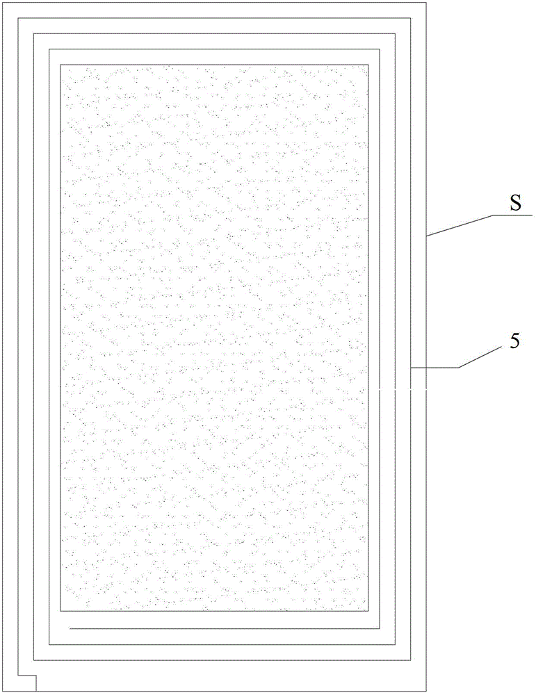
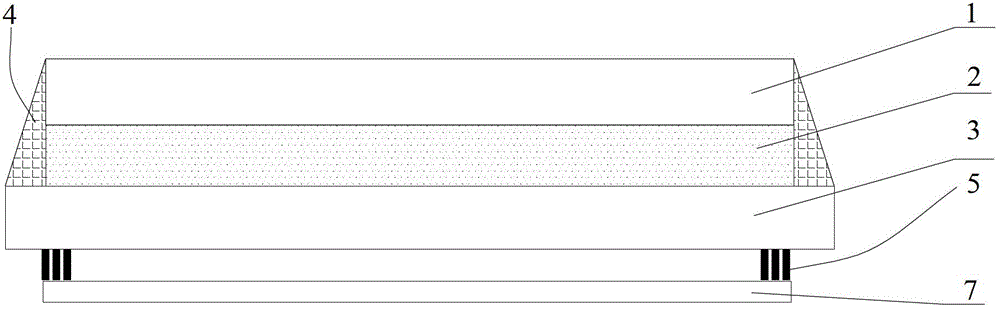
[0029] see also Figure 1a , Figure 1b , represents the NFC antenna installation structure of Embodiment 1 of the electrophoretic display integrated with the NFC antenna of the present invention. The display screen S of the electrophoretic display integrated with the NFC antenna includes a protective film (Protective Film) 1, an electrophoretic display film (EPD Film) 2 and a driving board 3, and the driving board 3 is a PCB, an FPC, a thin film field effect transistor array (TFT Array ), indium tin oxide (ITO) glass or one of ITO plastic plates, wherein the surrounding edges between the protective film 1 and the driving board 3 are encapsulated with a sealant 4 (Glue), forming an accommodating space to fill the electrophoretic display film 2; The NFC antenna 5 is arranged on the outer surface of the driving board 3 , and a protective layer 7 is arranged outside the NFC antenna 5 .

[0030] The NFC antenna 5 is arranged on the outside of the drive plate 3 of the display scre...

Embodiment 2

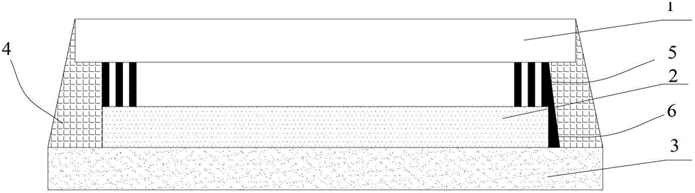
[0033] see figure 2 , represents the NFC antenna installation structure of Embodiment 2 of the electrophoretic display integrated with the NFC antenna of the present invention. The NFC antenna 5 is arranged on the inner side of the protective film 1 of the display screen, that is, between the protective film 1 and the electrophoretic display film 2, and the NFC antenna 5 is electrically connected to the output circuit of the driving board 3 of the display screen, specifically It is connected to the output line 3 of the driving board through the conductive silver paste or other conductive material 6 on one side of the electrophoretic display film. Other structures are the same as those in Embodiment 1, and will not be repeated here.

Embodiment 3

[0035] see image 3 , represents the NFC antenna installation structure of Embodiment 3 of the electrophoretic display integrated with the NFC antenna of the present invention. The NFC antenna 5 is arranged on the outer surface of the protective film 1 of the display screen, and a protective layer 7 is arranged outside the NFC antenna 5 , and is connected to the output line of the driving board 3 through the conductive silver paste 6 . Other structures are the same as those in Embodiments 1 and 2, and will not be repeated here.


PUM


Abstract

The invention relates to NFC (Near Field Communication) technology and particularly discloses an electrophoretic display integrated with an NFC antenna. The NFC antenna is arranged on the display screen of the electrophoretic display, and an NFC interface is piggybacked on an output line of the display screen and connected with a master control board of the display screen. The electrophoretic display integrates the functions of the display screen and the NFC antenna, and can solve the problems that the NFC antenna has poorer signal quality and failed receiving due to wear of the antenna and non-alignment by directly arranging the NFC antenna on the electrophoretic display, and additionally, provide a solution scheme for conveniently receiving the NFC signal from the display interface of the display, or necessarily receiving the NFC signal from the display interface of the display.

Description

[0001] The present invention claims the priority of the Chinese patent application with the application number "201220145136.8" and the title "a display screen" filed by the applicant Truly Semiconductor Co., Ltd. on April 06, 2012, the entire content of which is incorporated in the present invention . technical field [0002] The invention relates to the technical field of near field communication, in particular to an electrophoretic display integrated with an NFC antenna. Background technique [0003] The NFC (Near Field Communication, Near Field Communication) technology is an essential technology for electronic products in the future, and has a huge market. The antenna of existing NFC products is mainly made on one side of the battery, or attached to the inside of the casing, usually on the PCB (Printed Circuit Board, printed circuit board) or FPC (Flexible Printed Circuit, flexible circuit board) , make a coil with metal traces, and then paste the PCB or FPC containing...

Claims


Application Information

Patent Timeline
Patent Type & Authority Applications(China)
IPC IPC(8): G09F9/37G02F1/167H01Q1/22H05B44/00
CPCH01Q7/00H01Q1/22H01Q1/44H05K5/02G02F1/133H10K59/40H10K59/871H04B5/26H05B45/60H10K59/00H01Q1/40H01Q1/50G02F1/133345G02F1/13338G02F1/133512G02F1/133514G02F1/1368H01Q1/2266H05K1/181H05K1/189H05K2201/10098H05K2201/10151G02F1/13306G09G3/344G09G2370/00H01Q1/2258H01L27/124H01Q1/2283
Inventor 李建华王东岳毛航超梁永超李赣湘陈学彬
Owner TRULY IND LTD
Features
  • R&D
  • Intellectual Property
  • Life Sciences
  • Materials
  • Tech Scout
  • Unparalleled Data Quality
  • Higher Quality Content
  • 60% Fewer Hallucinations
Learn More