Electronic adjustment device, electronic adjustment control system and electronic adjustment control method
An ESC device and ESC control technology, which is applied in the field of communication, can solve problems such as increased labor costs and material costs, unsightly appearance of the antenna, and complicated wiring structure, etc., achieving simple and beautiful packaging appearance, various combination methods, Configure flexible effects
- Summary
- Abstract
- Description
- Claims
- Application Information
AI Technical Summary
Problems solved by technology
Method used
Image

Examples
Embodiment 1
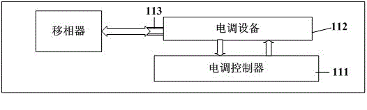
[0037] Such as figure 1 As shown, an electric regulation device provided by an embodiment of the present invention includes a transmission part 113, an electric regulation device 112 and an electric regulation controller 111, and the electric regulation device 112 includes a motor; the electric regulation controller 111 and the electric regulation controller 111 The device 112 is connected, the motor of the electric adjustment device 112 is connected with the transmission part 113, and the transmission part 113 is connected with the adjustment part of the phase shifter in the electric adjustment antenna; the electric adjustment controller 111 drives the motor to rotate and drives the transmission part 113, and then The transmission part 113 drives the adjustment part of the phase shifter in the electric adjustable antenna to move, so as to adjust the downtilt angle of the antenna.
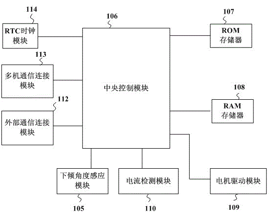
[0038] Specifically, such as figure 2 As shown, the ESC controller 111 includes a central con...
Embodiment 2
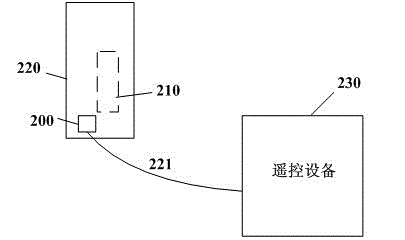
[0050] Such as image 3 and Figure 4 As shown, the embodiment of the present invention provides an electric regulation control system, including a remote control device 230, a link component 200, and the electric regulation device 210 described in Embodiment 1, wherein there are multiple electric regulation devices 210. The link component 200 is a passive connection device with multiple communication ports, and each communication port is connected in a star shape in the link component 200 . An electric regulation device 210 can be installed in each sector of a multi-sector electric regulation antenna 220 , and then the electric regulation controllers of all the electric regulation devices 210 and the remote control device 230 are connected to each other through the link component 200 . In particular, the remote control device 230 is connected to the link component 200 through the AISG connection line 221 .
[0051] When installing the ESC control system provided in this emb...
PUM
 Abstract
Description
Claims
Application Information
 - Generate Ideas
- Intellectual Property
- Life Sciences
- Materials
- Tech Scout
- Unparalleled Data Quality
- Higher Quality Content
- 60% Fewer Hallucinations
Browse by: Latest US Patents, China's latest patents, Technical Efficacy Thesaurus, Application Domain, Technology Topic, Popular Technical Reports.
© 2025 PatSnap. All rights reserved.Legal|Privacy policy|Modern Slavery Act Transparency Statement|Sitemap|About US| Contact US: help@patsnap.com