Method for time synchronization in a communication network

A technology of time synchronization and communication network, applied in the field of communication network, it can solve the problems of unknown frequency and time delay of measurement error of single clock change, inability to coordinate the reference clock, and non-continuous curve trend.

Inactive Publication Date: 2012-10-24
SIEMENS AG
View PDF5 Cites 13 Cited by
  • Summary
  • Abstract
  • Description
  • Claims
  • Application Information

AI Technical Summary

Problems solved by technology

[0004] The problem with the synchronization of clocks explained above is that secondary nodes cannot The internal clock of the master node cannot be accurately coordinated with the base clock of the master node
Wherein, according to the first cycle counting state, the curve trend of the corresponding second cycle counting state of the second node is not continuous, and there will be a fault when receiving a new synchronization message that will cause a synchronization update

Method used


Image

  • Method for time synchronization in a communication network
  • Method for time synchronization in a communication network
  • Method for time synchronization in a communication network

Examples


Embodiment Construction

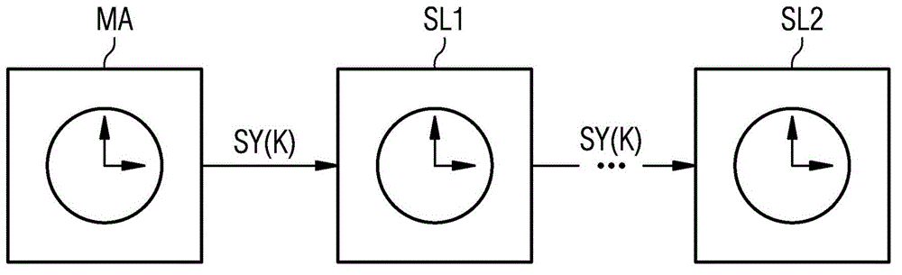
[0048] figure 1 A chain of nodes in a communication network in which an embodiment of the method according to the invention is carried out is shown. The communication network comprises a first node in the form of a so-called master node MA and a plurality of second nodes in the form of so-called auxiliary nodes, wherein in figure 1 Two secondary nodes SL1 and SL2 are shown in . The master node MA includes a reference clock which generates a reference clock frequency. In contrast to this, the individual secondary nodes SL1 , SL2 etc. comprise individual internal clocks which generate corresponding internal clock frequencies. in accordance with figure 1 In the communication network, use a suitable time synchronization protocol, such as the PTP protocol according to the IEEE 1588 standard (PTP=Precision Time Protocol (precision time protocol)), to synchronize the internal clock of each secondary node with the reference clock of the primary node MA . To this end, the synchron...


PUM


Abstract

The invention relates to a method for time synchronization in a communication network having a plurality of nodes (MA, SL1, SL2, SLn), the nodes (MA, SL1, SL2, SLn) comprising a first node (MA) and one or more second nodes (SL1, SL2, SLn), the first node (MA) generating first cycle counting states according to a reference cycle frequency and the one or more second nodes (SL1, SL2, SLn) each generating second cycle counting states according to an internal cycle frequency, wherein time synchronization is carried out in consecutive synchronization cycles, in which synchronization messages (SY (k)) are consecutively transferred from a node (MA, SL1, SL2, SLn) to a further node (MA, SL1, SL2, SLn) starting from the first node (MA) and a synchronization message (SY (k)) transmitted by a node (MA, SL1, SL2, SLn) contains a piece of information (SI, SI'), which is used for time synchronization in the node (SL1, SL2, SLn) receiving the synchronization message (SY (k)). The method is characterized in that, in a particular second node (SLn), a time synchronization is performed based on an estimate of a first cycle counting state in combination with a linear-quadratic regulator (LQR), the estimate preferably being based on a Kalman filter (KF). In this manner, a synchronized time is obtained in the form of a controlled first cycle counting state (CF). The method is suitable in particular for time synchronization in communication networks for industrial automation systems, wherein the processes carried out in the automation system must be exactly coordinated.

Description

technical field [0001] The invention relates to a method for time synchronization in a communication network, as well as a node in the communication network and a corresponding communication network. Background technique [0002] In many technical fields, communication networks are used to automate processes that are distributed over multiple units. It is extremely important here, especially in industrial automation networks, that the automatic programs be precisely coordinated with one another. To this end, the individual nodes in the communication network include corresponding clocks, which are synchronized with the reference clock in the reference node. A reference node is also usually called a primary node, conversely other nodes with an internal clock are usually called secondary nodes. [0003] The protocols disclosed in the prior art for synchronizing clocks in communication networks are specified in the industrial IEEE 1588, IEC 61158 and IEEE 802.1AS standards. A...

Claims


Application Information

Patent Timeline
Patent Type & Authority Applications(China)
IPC IPC(8): H04J3/06
CPCH04J3/0664H04J3/0673G06F1/14
Inventor 那崇宁德拉甘·奥布拉多维奇鲁克桑德拉·沙伊特尔菲利普·沃尔夫鲁姆
Owner SIEMENS AG
Why Eureka
Try Eureka