Installing structure of high-efficiency air filter

A technology of high-efficiency air and installation structure, applied in the direction of suction filter, etc., can solve the problems of cumbersome installation of hepa, burnout of vacuum motor, and many complicated parts, and achieve the effect of simple and stable structure, ensuring correct installation and convenient use

Inactive Publication Date: 2012-10-31
LG ELECTRONICS (TIANJIN) APPLIANCES CO LTD
View PDF2 Cites 2 Cited by
  • Summary
  • Abstract
  • Description
  • Claims
  • Application Information

AI Technical Summary

Problems solved by technology

When there is a lot of dust in the filter, it is necessary to remove the filter and clean the filter; and when the filter is missing, if the user turns on the vacuum cleaner, the air that is discharged from the separation chamber and has not been finally filtered will carry dust into the vacuum motor, often It will cause the vacuum motor to burn out
[0004] Chinese patent 200820041592.1 discloses a vacuum cleaner filter leakage protection device, which includes an accommodation cavity with a cover in the main body of the vacuum cleaner and a dust collection box placed in the storage cavity; the upper cover is formed with at least one upper cover Sealing ribs; a filter is installed at the rear of the dust box; a pop-up device is also installed at the rear of the dust box, and the pop-up device includes a pop-up piece that can be popped up, and a baffle that prevents the pop-up piece from being ejected is formed on the filter. part; when the filter is missing, the pop-up piece pops out, and the sealing rib of the upper cover is against the pop-up piece so that the upper cover cannot cover the accommodating cavity
[0006] However, the hepa leak-proof installation device in the prior art has a complex structure and many parts, resulting in many adverse situations, and causes cumbersome operations when installing the hepa, which reduces the customer's experience in using the product

Method used


Image

  • Installing structure of high-efficiency air filter
  • Installing structure of high-efficiency air filter
  • Installing structure of high-efficiency air filter

Examples


Embodiment Construction

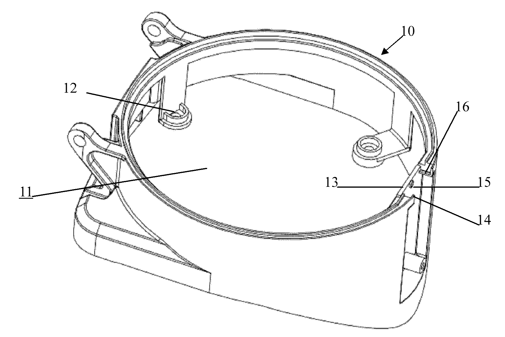
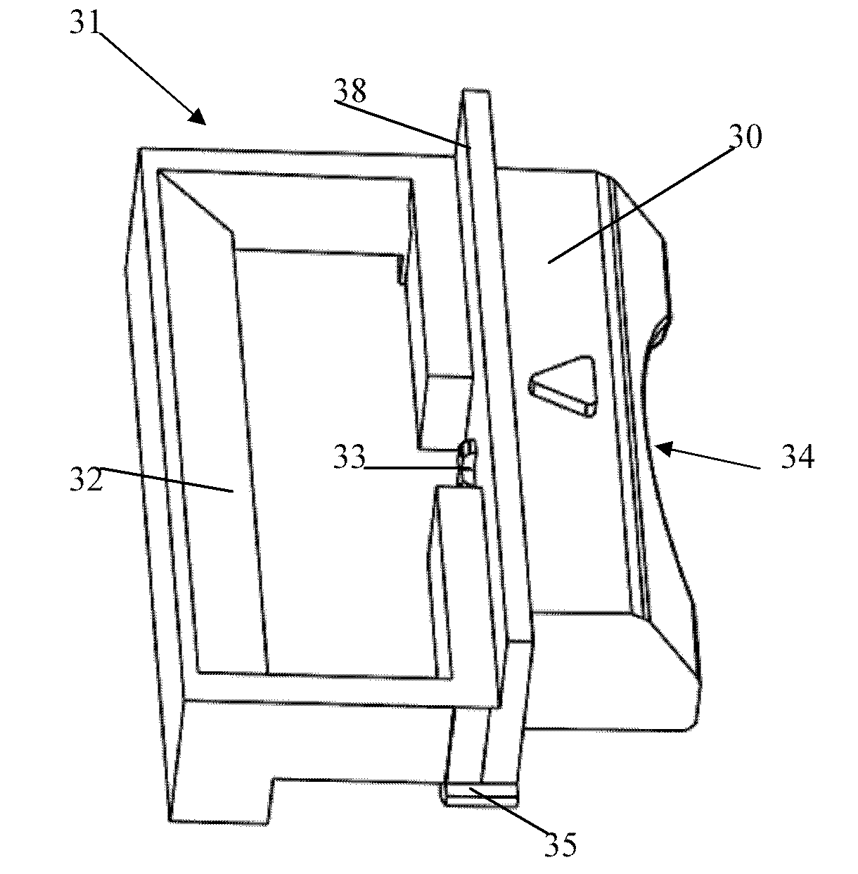
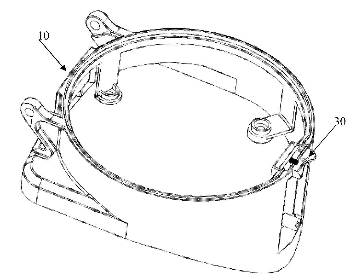
[0020] The structure of the present invention will be described in detail below in conjunction with the accompanying drawings.

[0021] Such as Figure 1-4 As shown, the installation structure of the high-efficiency air filter of the present invention includes: a shroud 10 that guides the airflow to the motor cavity, a high-efficiency air filter 20 that can be embedded in the installation port 11 of the shroud 10, and The split sliding bayonet structure 30 is arranged on the upper edge of the installation port 11 of the wind deflector. The wind deflector 10 includes the installation port 11 of the high-efficiency air filter 20, and a plurality of support claws 12 integrally formed with the wind deflector 10 and extending inward. The support claws 12 can effectively support the high-efficiency air filter installed in place. The lower edge of the filter effectively ensures the stability of the high-efficiency air filter. The installation opening 11 is a cylindrical structure f...


PUM


Abstract

The invention discloses an installing structure of a high-efficiency air filter. The installing structure comprises a guide flow cover and the high-efficiency air filter, wherein the guide flow cover guides the airflow into a motor cavity; the high-efficiency air filter can be embedded into an installing port in a matching manner; the installing port is of a cylindrical structure forming a section of linear cutting edge; two sliding grooves are arranged on the linear cutting edge; a bayonet structure can be arranged on the linear cutting edge in a front-rear sliding manner; an elastic component is arranged between the bayonet structure and the linear cutting edge so as to enable the bayonet structure to extend outwards; and the shape of a shell of the high-efficiency air filter is the cylindrical structure which corresponds to the installing port and is provided with the linear cutting edge. The installing structure disclosed by the invention has the advantages that the anti-leakage structure of the high-efficiency air filter is adopted, the bayonet structure is designed into a split type sliding structure, and the position can be correspondingly changed according to the installation or not of the high-efficiency air filter; the structure is simple and stable, the use is convenient, the correct installation of the high-efficiency air filter can be effectively guaranteed, and the motor can be prevented from being damaged due to entering of fine dust.

Description

technical field [0001] The invention relates to the field of vacuum cleaners, in particular to a leak-proof structure of a filter device of the vacuum cleaner. Background technique [0002] Generally, a vacuum cleaner is a device that uses a vacuum to generate suction to inhale air, make the air flow through various filters, filter foreign objects in the air, and clean the room. [0003] In the prior art, a high-efficiency air filter (hepa) is usually installed on the air outlet at the rear of the dust collection box in the vacuum cleaner to filter the air that is about to be sucked into the vacuum motor after being discharged from the separation chamber. When there is a lot of dust in the filter, it is necessary to remove the filter and clean the filter; and when the filter is missing, if the user turns on the vacuum cleaner, the air that is discharged from the separation chamber and has not been finally filtered will carry dust into the vacuum motor, often It will cause t...

Claims


Application Information

Patent Timeline
IPC IPC(8): A47L9/10
Inventor 赵晓军
Owner LG ELECTRONICS (TIANJIN) APPLIANCES CO LTD
Why Eureka
Try Eureka