
Proximity switch device

A proximity switch and wire connection technology, applied in the field of switchgear, can solve the problems of complex structure, short service life, low reliability, etc., and achieve the effects of simple and firm structure, long service life and not easy to damage

Inactive Publication Date: 2014-06-11
DALIAN TIANXIANG ELECTRICAL APPLIANCE MFG
View PDF0 Cites 0 Cited by
  • Summary
  • Abstract
  • Description
  • Claims
  • Application Information

AI Technical Summary

Problems solved by technology

[0002] There are more and more types of switches used in the field of electrical control. Traditional spring switch devices usually have complex structures, poor opening and closing effects, easy damage, short service life, and low reliability, which brings inconvenience to use and maintenance.

Method used


Image

  • Proximity switch device

Examples


Embodiment Construction

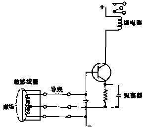
[0008] The principle of the proximity switch device of the present invention is as figure 1 As shown, the sensitive coil is connected to the input end of the oscillator through a wire, the output end of the oscillator is connected to the relay device through a triode amplifier, and a magnetic field is provided at the end of the sensitive coil. The proximity switch device of the present invention generates electric energy through the induction magnetic field of the sensitive coil, the electric energy is connected to the oscillator through the wire, the oscillator is connected to the relay through the triode amplifier, and the opening and closing of the switch is controlled by the opening and closing of the relay. The whole switch device has a simple structure, simple and firm structure .


PUM


Abstract

Provided is a proximity switch device. A sensitive coil is connected with the input end of an oscillator through a wire. The output end of the oscillator is connected with a relay set through a triode amplifier. A magnetic field is formed at the end of the sensitive coil. According to the proximity switch device, the sensitive coil senses the magnetic field to generate electric energy, the electric energy is transmitted to the oscillator through the wire, the oscillator is connected with the relay set through the triode amplifier, and the switch is controlled to be opened or closed by switching on or switching off the relay. The whole proximity switch device is simple and firm in structure, high in reliability, not prone to damage and long in service life.

Description

technical field [0001] The invention relates to the field of electrical control equipment, in particular to a switch device. Background technique [0002] There are more and more types of switches used in the field of electrical control. Traditional spring switch devices usually have complex structures, poor opening and closing effects, easy damage, short service life, and low reliability, which brings inconvenience to use and maintenance. Contents of the invention [0003] In order to overcome the above-mentioned problems existing in the traditional switch device, the present invention provides a proximity switch device with a simple structure. [0004] The technical solution adopted by the present invention to achieve the above object is: a proximity switch device, the sensitive coil is connected to the input end of the oscillator through a wire, and the output end of the oscillator is connected to the relay device through a triode amplifier. [0005] The end of the...

Claims


Application Information

Patent Timeline
IPC IPC(8): H03K17/95
Inventor 郑宸陈淑娟徐萌李明君
Owner DALIAN TIANXIANG ELECTRICAL APPLIANCE MFG
Learn More