Urine sampling device for urinary surgery
A technology of urology and sampling device, which is applied in the field of medical equipment, can solve the problems of urine splashing, tube body falling on hands, urine pollution, etc., achieve simple and stable structure, avoid urine splashing everywhere, and high universality Effect
- Summary
- Abstract
- Description
- Claims
- Application Information
AI Technical Summary
Problems solved by technology
Method used
Image
Examples
Embodiment 1
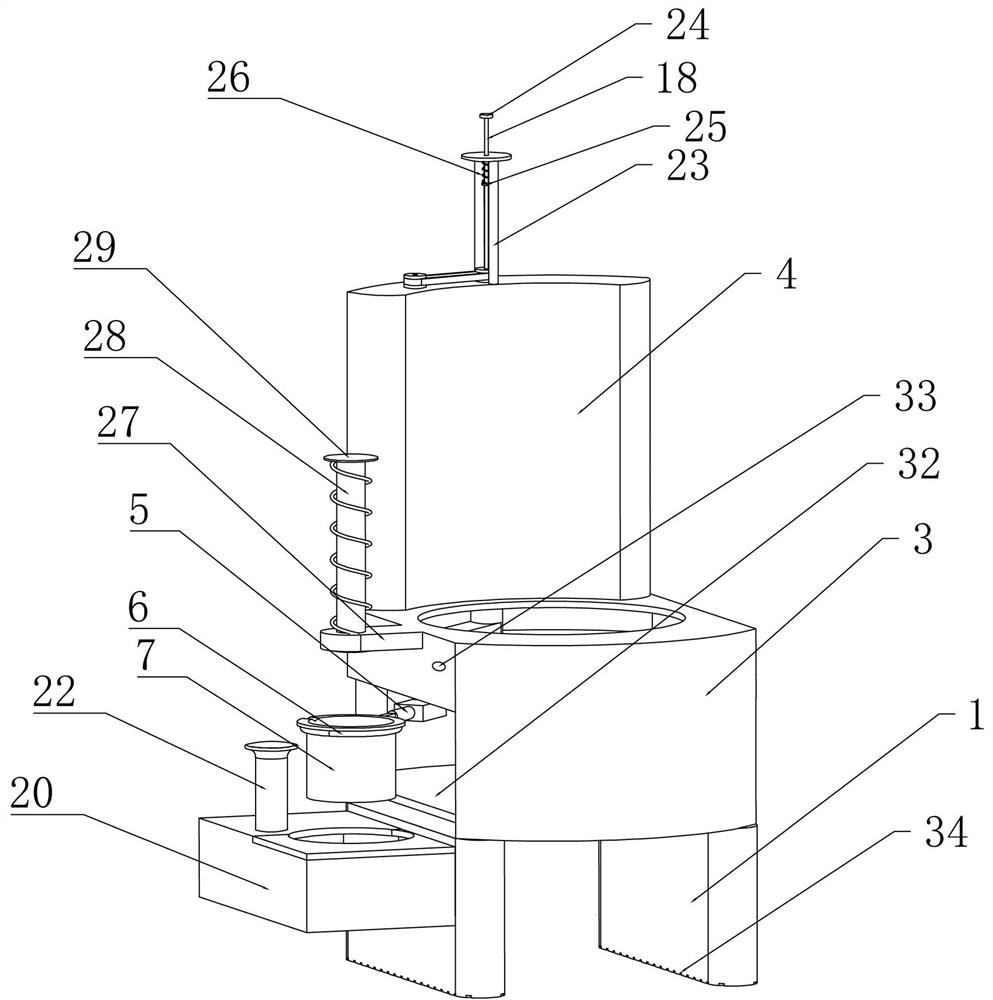
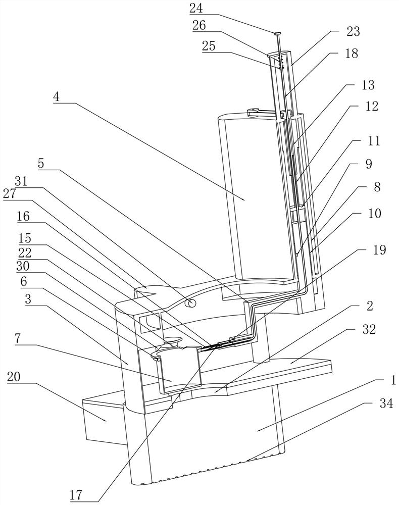
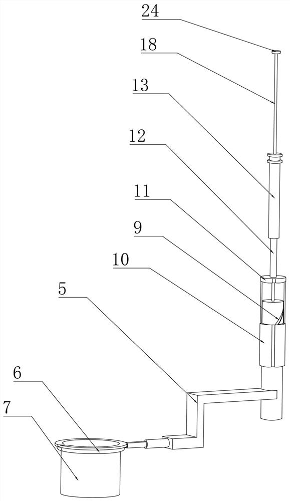
[0033] Embodiment 1. The present invention is a urine sampling device for urology, which includes a support base 1. The support base 1 is placed on the ground to provide a fixed support foundation for subsequent structures. The upper end of the support base 1 is provided with a The urination hole 2 enables urine to flow to the inside of the urination duct through the urination hole 2, and the upper end of the support seat 1 is fixedly connected with an upper support 3, and the patient is supported by the upper support 3, At the same time, the female patient can be seated on the upper support 3 to realize the sampling of urine. The upper end of the upper support 3 is fixedly connected with a protective cover 4, and the protective cover 4 realizes the The protection of the structure of the upper end of the upper support 3, the rear end of the upper support 3 is rotatably connected with the rotating crank 5 placed between the support base 1 and the upper support 3, and the rotatin...
Embodiment 2
[0036] Embodiment 2, on the basis of Embodiment 1, when the urine cup 7 is transported to the outside world, the patient needs to remove the urine cup 7 by hand and pour it into the test tube 22, which will cause The urine splashed on the urine cup 7 adheres to the hands, and at the same time, the pouring process or hand tremors cause the urine to pollute the urine cup 7 and the test tube 22. Therefore, this embodiment provides a A structure for automatically dumping urine. Specifically, the rotating tray 6 is fixedly connected with a rotating cam sleeve 15 near the rotating crank 5, and the rotating cam sleeve 15 is rotatably connected to the rotating crank 5. Inside, the rotating cam sleeve 15 can rotate inside the rotating crank 5 to realize the synchronous rotation of the rotating tray 6, and then drive the synchronous rotation of the urine receiving cup 7 to realize the synchronous rotation of the urine receiving cup 7. To dump the urine in the cup 7, the inner wall of th...
Embodiment 3
[0039] Embodiment 3, on the basis of Embodiment 2, since the stay cord 18 shrinks to a certain extent during the rotation of the crank 5, in order to ensure that the stay cord 18 is always tight state, to ensure that when the pull cord 18 is pulled, the rotating cam sleeve 15 can be driven to rotate immediately, so this embodiment provides a structure to ensure that the stay cord 18 is always in a tight state, specifically, The upper end of the protective cover 4 is fixedly connected with a limit bracket 23, the stay cord 18 runs through the limit bracket 23, and the upper end of the stay cord 18 is fixedly connected with a stopper placed at the upper end of the limit bracket 23. The pull ring plate 24 realizes the pulling of the pull-up through the pull ring plate 24, and the pull ring plate 24 prevents the stay rope 18 from passing through the stop bracket 23, resulting in The stay cord 18 falls off;
[0040] The lower end of the limiting bracket 23 is provided with a limit...
PUM
 Abstract
Description
Claims
Application Information
 - R&D
- Intellectual Property
- Life Sciences
- Materials
- Tech Scout
- Unparalleled Data Quality
- Higher Quality Content
- 60% Fewer Hallucinations
Browse by: Latest US Patents, China's latest patents, Technical Efficacy Thesaurus, Application Domain, Technology Topic, Popular Technical Reports.
© 2025 PatSnap. All rights reserved.Legal|Privacy policy|Modern Slavery Act Transparency Statement|Sitemap|About US| Contact US: help@patsnap.com


