Permanent magnet assembly fixture for large permanent magnet direct-driven wind generator and assembly method of permanent magnet assembly fixture

A wind turbine, permanent magnet direct drive technology, used in metal processing, manufacturing tools, workpiece clamping devices, etc., can solve the problems of surface damage of permanent magnet pole pieces, risk of fan operation, difficult to assemble in place, etc., and achieve convenient movement. , high safety, simple use conditions

Active Publication Date: 2014-12-10
GUODIAN UNITED POWER TECH
View PDF8 Cites 0 Cited by
  • Summary
  • Abstract
  • Description
  • Claims
  • Application Information

AI Technical Summary

Problems solved by technology

[0003] As the main part of the large direct-drive permanent magnet wind turbine, the permanent magnet is easy to fly out or directly into the assembly position between the two sets of pole pieces during the direct assembly process due to its strong magnetic force and strong adsorption capacity. Adsorption on the surface of the pole piece not only causes damage to the permanent magnet itself and the surface of the pole piece, but also is not easy to be directly assembled in place. While the assembly is difficult, it also brings great risks to the operation of the fan

Method used


Image

  • Permanent magnet assembly fixture for large permanent magnet direct-driven wind generator and assembly method of permanent magnet assembly fixture
  • Permanent magnet assembly fixture for large permanent magnet direct-driven wind generator and assembly method of permanent magnet assembly fixture
  • Permanent magnet assembly fixture for large permanent magnet direct-driven wind generator and assembly method of permanent magnet assembly fixture

Examples


Embodiment Construction

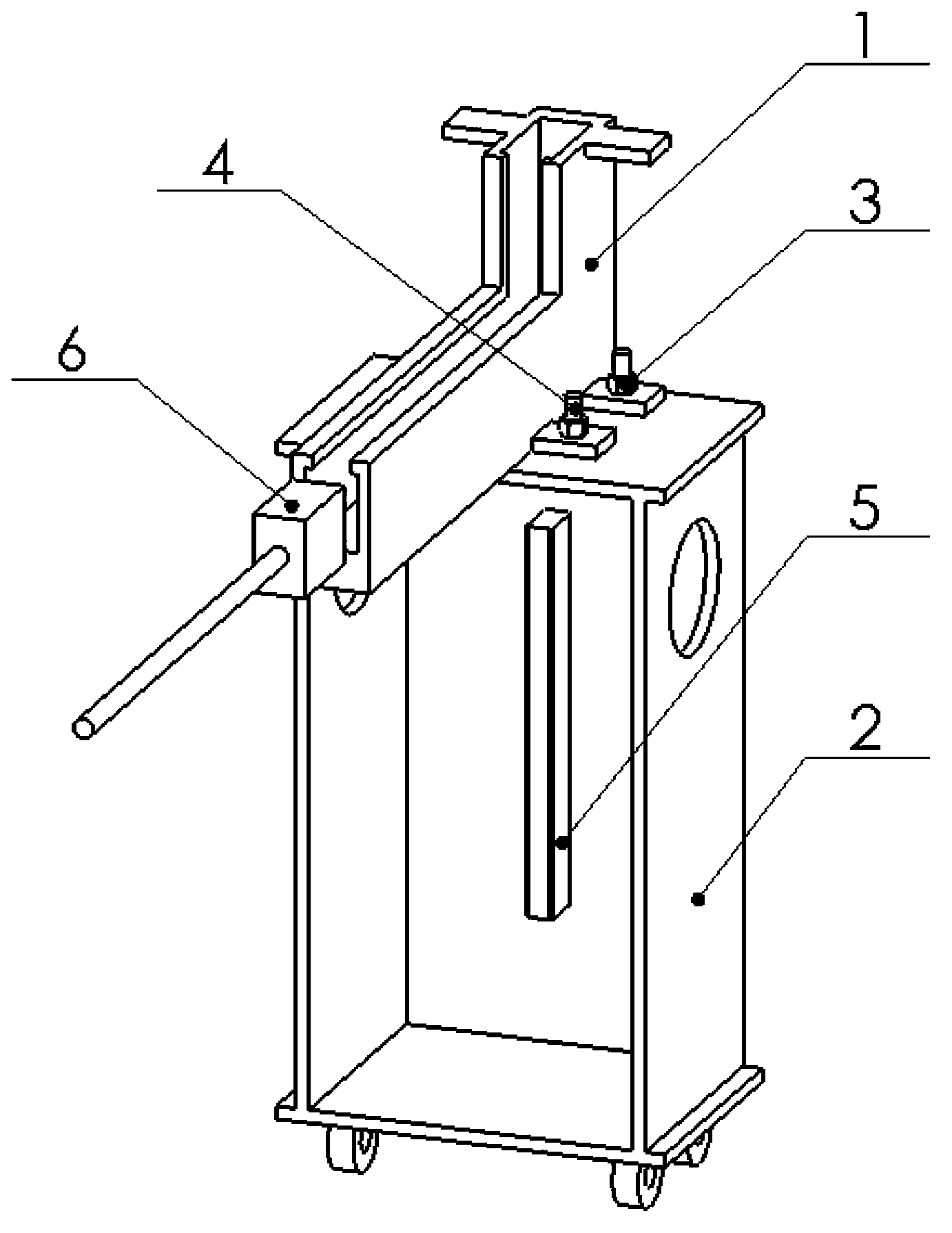
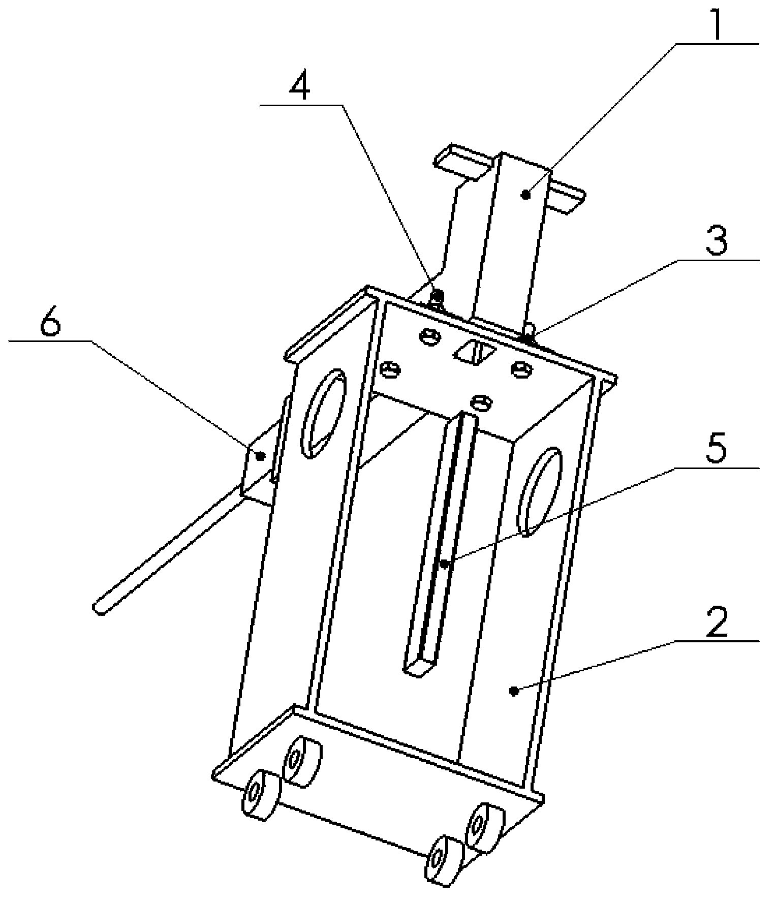
[0023] see figure 1 , figure 2 As shown, a permanent magnet assembly tool for a large permanent magnet direct drive wind power generator according to the present invention mainly includes a bracket 2 , a permanent magnet guide groove 1 and a conductive rod 5 . The permanent magnet guide groove 1 is L-shaped, includes a horizontal section and a vertical section, and is fixedly installed above the bracket 2 . The conducting rod 5 can be slidably installed in the bracket 2 up and down, and a conducting hole corresponding to the top of the conducting rod 5 is provided on the bracket 2 and the permanent magnet guide groove 1 . After assembly, the conduction rod 5 can smoothly pass through the conduction hole of the permanent magnet guide groove 1 and the roller bracket 2 .

[0024] Wherein, the shape of the permanent magnet guide groove 1 should match the shape of the permanent magnet, and an appropriate tolerance is selected to ensure that the permanent magnet can pass through ...


PUM


Abstract

The invention relates to a permanent magnet assembly fixture for a large permanent magnet direct-driven wind generator and an assembly method of the permanent magnet assembly fixture, wherein the fixture comprises a bracket, a permanent magnet guide groove and a conducting rod; the permanent magnet guide groove is L-shaped, and is fixedly arranged above the bracket; the conducting rod is slidably arranged inside the bracket up and down; and conducting holes corresponding to the top end of the conducting rod are formed on the bracket and the permanent magnet guide groove. The method comprises the following steps of: placing the rotor of the generator on a mounting platform so that the assembly port of a permanent magnet faces downwards; arranging the fixture below the rotor of the generator, wherein the outlet of the vertical section of the permanent magnet guide groove is opposite to the assembly port of the permanent magnet; feeding in the permanent magnet from the inlet of the horizontal section of the permanent magnet guide groove, and pushing till reaching the bottom of the vertical section of the permanent magnet guide groove; pushing the conducting rod to slide upwards, and pushing the permanent magnet to enter the middle of pole terminals along the vertical section of the permanent magnet guide groove; and taking out the conducting rod. The permanent magnet assembly fixture for a large permanent magnet direct-driven wind generator and the assembly method of the permanent magnet assembly fixture can realize the direct assembly of the permanent magnet between two sets of pole terminals, and the operation is convenient, safe and reliable.

Description

technical field [0001] The invention relates to an assembly tool for a large generator and an assembly method using the tool, in particular to a permanent magnet assembly tool for a large permanent magnet direct drive wind power generator and an assembly method thereof. Background technique [0002] At present, wind power generators are developing in the direction of high reliability, low maintenance, reduced components, lower costs, high efficiency, and high integration. The general trend is that the capacity of a single machine continues to increase. In variable-speed constant-frequency wind power generation systems, double-fed asynchronous generators and permanent magnet synchronous generators are mostly used. In recent years, direct drive and brushless generators have attracted more and more attention. Direct drive permanent magnet wind turbines based on variable speed operation, variable pitch adjustment, low speed, high efficiency, and high power factor have become th...

Claims


Application Information

Patent Timeline
Patent Type & Authority Patents(China)
IPC IPC(8): B25B11/00B23P19/00
Inventor 武尧尧高宏志苏剑涛肖珊彩
Owner GUODIAN UNITED POWER TECH
Why Eureka
Try Eureka