
Buffer device of hydraulic oil cylinder

A technology of hydraulic cylinders and buffer devices, applied in the field of hydraulic cylinders, can solve problems such as equipment vibration, and achieve the effects of preventing cylinder cavitation, small size, and convenient installation

Inactive Publication Date: 2012-10-31
湖南瑞龙重工科技有限公司
View PDF9 Cites 21 Cited by
  • Summary
  • Abstract
  • Description
  • Claims
  • Application Information

AI Technical Summary

Problems solved by technology

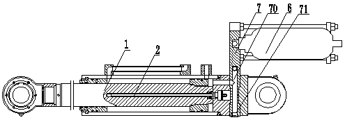
During the movement, due to the unevenness of the ground, the acceleration and deceleration actions and the vibration from the equipment itself, the equipment will vibrate, which will generate a large impact on the hydraulic cylinder in a rigid state, which will improve the comfort of the operator. Sexuality, reducing the maintenance cycle and maintenance costs of equipment will bring adverse effects

Method used


Image

  • Buffer device of hydraulic oil cylinder
  • Buffer device of hydraulic oil cylinder
  • Buffer device of hydraulic oil cylinder

Examples


Embodiment Construction

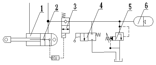
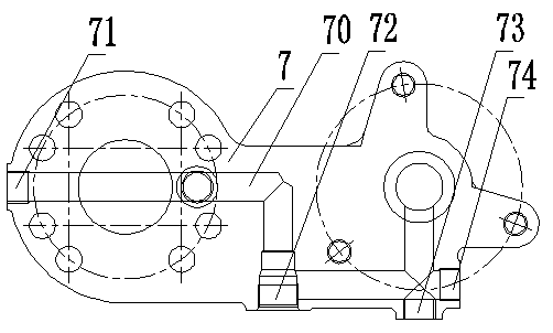
[0020] Such as figure 1 The hydraulic cylinder buffer device shown includes a hydraulic cylinder 1; a connecting block 7; a solenoid valve 3; an accumulator 6, the first end of the connecting block 7 is connected to the hydraulic cylinder 1, and the second end is connected to the accumulator The energy accumulator 6 is connected, and the connecting block 7 has a through hole 70 communicating with the rodless chamber of the hydraulic cylinder 1 and the accumulator 6 . The connecting block 7 communicates with the rodless chamber of the hydraulic cylinder 1 and the through hole 70 of the accumulator 6 has a fourth connecting port 71 leading to the outside of the first end of the connecting block 7; the through hole 70 has a U-shaped section, and the The first bend at the bottom of the U-shaped section has a first connection port 72 leading to the outside of the connecting block 7, and there is a second connecting port 73 and a third connecting port leading to the outside of the c...


PUM


Abstract

A buffer device of a hydraulic oil cylinder is provided with the hydraulic oil cylinder (1), a connecting block (7), a solenoid valve (3) and an energy accumulator (6). A first end of the connecting block (7) is connected with the hydraulic oil cylinder (1), a second end of the connecting block (7) is connected with the energy accumulator (6), the connecting block (7) is provided with a through hole (70) enabling a rodless cavity of the hydraulic oil cylinder and the energy accumulator to be communicated, and the solenoid valve is used for achieving non-communication and communication of the through hole (70). When the through hole of the connecting block is communicated, the hydraulic oil cylinder has the buffer effect. When the through hole is not communicated, the hydraulic oil cylinder is located in a rigidity state.

Description

technical field [0001] The invention relates to the technical field of hydraulic cylinders, in particular to a buffer device for hydraulic cylinders. Background technique [0002] In some large-scale construction machinery, such as the scraper bucket of the active scraper, it depends on the hydraulic cylinder to raise and lower. The transport bucket is maintained at a certain station. During the movement, due to the unevenness of the ground, the acceleration and deceleration actions and the vibration from the equipment itself, the equipment will vibrate, which will generate a large impact on the hydraulic cylinder in a rigid state, which will improve the comfort of the operator. Sexuality, reducing the maintenance cycle and maintenance costs of equipment will bring adverse effects. Contents of the invention [0003] In order to overcome the defects of the prior art, the present invention provides a buffer device for the hydraulic cylinder, which can maintain the hydrauli...

Claims


Application Information

Patent Timeline
IPC IPC(8): F15B15/22F15B15/28
Inventor 何利红易国华
Owner 湖南瑞龙重工科技有限公司
Learn More