Shear type expansion bolt

一种膨胀螺栓、螺栓的技术,应用在螺栓、螺钉、螺母等方向,达到使用方便可靠、应用环境宽泛、容易加工制造的效果

Active Publication Date: 2014-08-13
裴春光
View PDF6 Cites 0 Cited by
  • Summary
  • Abstract
  • Description
  • Claims
  • Application Information

AI Technical Summary

Problems solved by technology

[0004] The technical problem to be solved by the present invention is to provide a scissor-type expansion bolt that can be applied to hollow bricks or porous light brick walls to achieve safe and firm fixation for the defects of existing traditional expansion bolts.

Method used


Image

  • Shear type expansion bolt
  • Shear type expansion bolt
  • Shear type expansion bolt

Examples


Embodiment 1

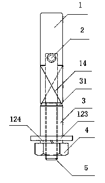
[0053] Such as figure 1 , 2 And shown in 3, the present invention comprises two expansion rods 1 that are semicircular in cross-section, and semicircular groove 6 and gap 7 are arranged on the expansion rod 1, and the upper end of expansion rod 1 is arc surface, and the bottom of expansion rod is provided with lower end slope 14 , the slope 14 at the lower end is facing inwardly; the two expansion rods 1 are hinged together with the upper end of the lug screw 5 through the riveting shaft 2, the hole on the upper end of the lug screw 5 is set on the riveting shaft 2, and 3 sets of wedges On the eared screw rod 5 and through the nut 4 screwed on one end of the screw rod 5, force is applied to push the lower end slopes of the two expansion rods 1 to make a scissors expansion movement, thereby achieving the purpose of anchoring or locking. The top end of the wedge 3 has a conical surface 31, and the taper of the conical surface 31 is consistent with the angle of the lower end slo...

Embodiment 2

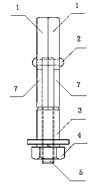
[0055] Such as Figure 4 , 5 As shown in and 6, the present invention includes two expansion rods 1 with a semicircular cross section, and a lug nut support 8; the lower section of the expansion rod 1 is provided with a concave plane 9, so that the two expansion rods 1 are combined and embedded in Between the two opposite support plates 81 of the lug nut support 8 ; the concave plane 9 ends of the two expansion rods 1 are inserted on the lug nut support 8 , and hinged to it by the riveting shaft 2 . The upper end of the expansion rod 1 is an arc surface, and the lower part of the expansion rod is provided with a lower end slope 14, and the lower end slope 14 is facing inwardly; The inclined surface 14 at the lower end makes it perform a scissors-type stretching movement, and then achieves the purpose of anchoring or locking. Limiting steps 82 are provided on the outer sides of the roots of the two oppositely arranged support plates 81 on the lug nut bearing 8, and the slope ...

Embodiment 3

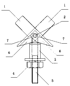
[0059] Such as Figure 7 , 8 As shown in and 9, this embodiment is basically the same as Embodiment 1, the difference is that the expansion rod 1 is replaced by an expansion plate 11, and there is no need to set semicircular grooves and gaps on the expansion plate 11. The present embodiment includes two expansion plates 11 whose both ends are sloped. The two expansion plates 11 lean against the two sides of the support plate of the lug screw 5 and are hinged by the riveting shaft 2. The wedges 3 are sleeved on the lugs. The screw rod 5 is given force by the nut 4, so as to push the slopes at the lower ends of the two expansion plates 11 to make them open in a scissor style, thereby achieving the purpose of anchoring or locking. If the eared screw 5 is set in the shape of double ears, two expansion plates 11 are embedded between the two ears (not shown).


PUM


Abstract

The present invention provides a shear expansion bolt that can be suitable for hollow or porous light brick walls to achieve secure and firm fixing, including fixed parts and promotions with expansion parts.Promote the same axis along the axis of the fixed part; the top part of the expansion parts and the top of the fixed parts, the lower end of the expansion part has a slope to the promoter.And push the expansion parts along the lower end of the expansion parts, so that the expansion parts are stretched outward.The structure of the present invention is simple and clever, easy to process and low processing costs, easy to use and reliable, not only can be used firmly and reliable on porous block walls, but also widely used in solid brick walls, earth walls, concrete structures, wooden structures, wooden structures, and wooden structures., Plastic structure, dense soil and other dense and honeycomb matrix anchors.

Description

technical field [0001] The invention relates to an expansion bolt in the field of fasteners. Background technique [0002] Since the British engineer John Joseph Rollins invented the expansion bolt in 1911, it has been used for a whole century. The expansion bolt is usually composed of countersunk head bolts, expansion tubes, washers, spring pads and hexagonal nuts. When in use, first use an impact electric drill (hammer) to drill holes of corresponding sizes on the fixed body, and then install the bolts and expansion tubes. Enter the hole, tighten the nut on the bolt, the bolt goes out, and the expansion tube outside does not move, so the big head of the countersunk bolt props up the end of the expansion tube with several cutouts, so that it fills the entire hole. In this way, the bolts, expansion tubes, mounting parts and fixed body are tightened into one. Although there are many new technical improvements based on the expansion bolt, almost all of the improvement schem...

Claims


Application Information

Patent Timeline
Patent Type & Authority Patents(China)
IPC IPC(8): F16B13/10F16B39/282
CPCF16B13/0808F16B13/04
Inventor 裴志胜裴春光王秀秀
Owner 裴春光
Why Eureka
Try Eureka