Check patentability & draft patents in minutes with Patsnap Eureka AI!

Direct Clutch Control for Dual Clutch Transmissions

A dual clutch and transmission technology, applied in the field of clutch systems, can solve problems such as difficulty in differences

Inactive Publication Date: 2017-04-19
GM GLOBAL TECH OPERATIONS LLC
View PDF2 Cites 0 Cited by
  • Summary
  • Abstract
  • Description
  • Claims
  • Application Information

AI Technical Summary

Problems solved by technology

As the clutch plates of the clutch wear, it becomes more difficult for these electronically controlled circuits to compensate for the difference between the desired clutch force and the force actually applied to the clutch

Method used


Image

  • Direct Clutch Control for Dual Clutch Transmissions
  • Direct Clutch Control for Dual Clutch Transmissions
  • Direct Clutch Control for Dual Clutch Transmissions

Examples


Embodiment Construction

[0043] The following description is merely exemplary in nature and is not intended to limit the disclosure, application or uses.

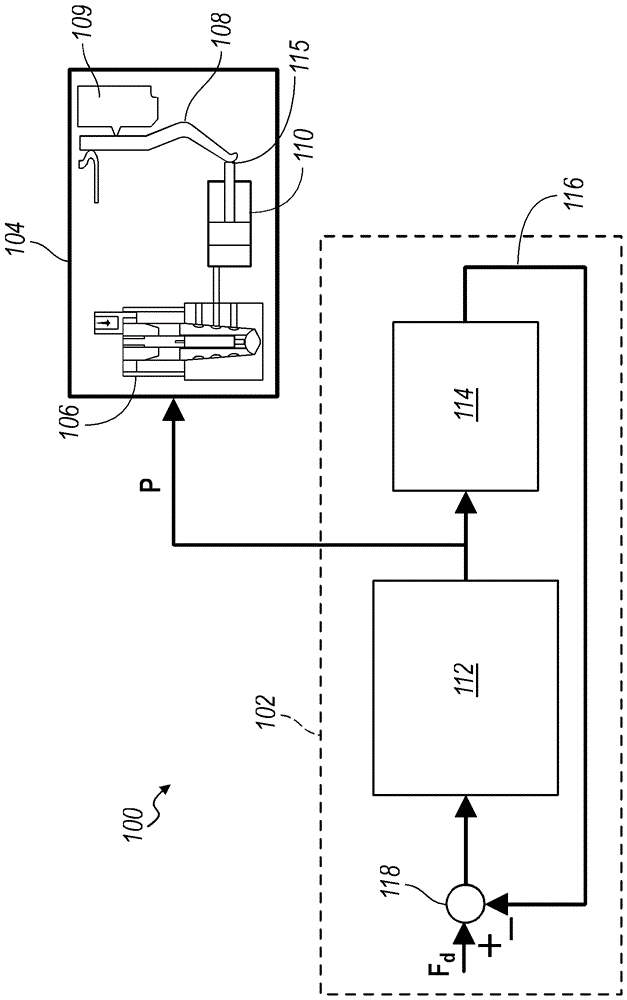
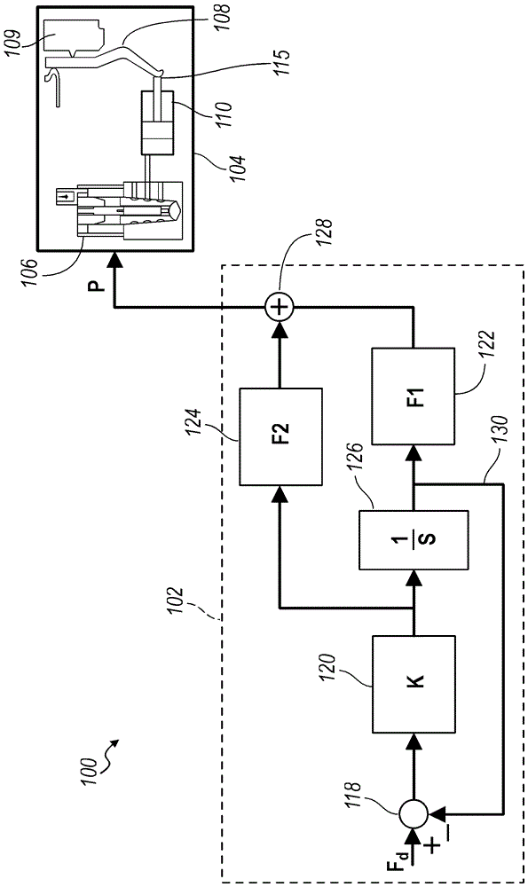
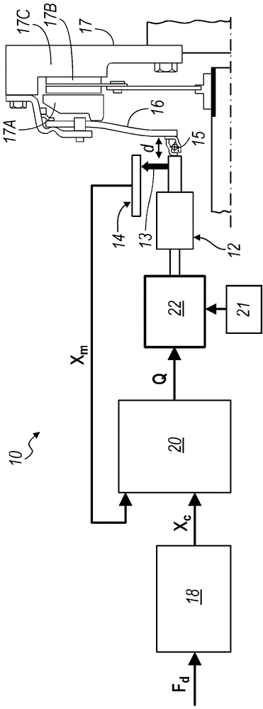
[0044] Referring now to the accompanying drawings, Figure 2 to Figure 4 A clutch control system embodying the principles of the present invention is shown in and indicated at 100, and, for comparison, at figure 1 A conventional clutch control system is shown in , indicated at 10 . These clutch control systems are associated with motor vehicle powertrains, especially dual clutch transmissions.

[0045] A conventional clutch control system 10 includes a hydraulic actuator 12 and a clutch pack 17 . The clutch pack 17 includes a set of clutch plates 17A, 17B, 17C and a diaphragm spring rod 16 . The diaphragm spring rod 16 is in contact with the clutch plate 17A and is coupled to the hydraulic actuator 12 with an applied bearing 15 close to or at the distal end of the diaphragm spring rod 16 .

[0046] System 10 also includes force-position transdu...


PUM


Abstract

The present invention provides a control system for controlling clutches of a dual clutch transmission comprising an internal model based force control algorithm, a pressure control valve, a hydraulic actuator and a clutch assembly, wherein the force control algorithm transforms a desired clutch force For the pressure control signal, the pressure control valve receives the pressure control signal, the pressure control valve applies pressure related to the pressure control signal to the hydraulic actuator, and the clutch assembly has a spring rod and a plurality of clutch plates. A hydraulic actuator applies a desired force to the distal end of the spring rod corresponding to the pressure control signal such that the desired force applied to the distal end of the spring rod applies the actual clutch force to the clutch plates.

Description

technical field [0001] The invention relates to a system for controlling a clutch in a motor vehicle transmission. More specifically, the present invention relates to direct clutch force control systems for dual clutch transmissions. Background technique [0002] The statements in this section merely provide background information related to the present disclosure and may or may not constitute prior art. [0003] A typical dual clutch transmission includes a pair of operating clutches that drive a pair of input shafts. The input shafts may be located on opposite sides of the output shafts, or may be concentrically located between spaced apart output shafts. A plurality of synchronizers selectively couples the rotatable gears to associated shafts to achieve forward and reverse gear ratios. Additionally, solenoid and valve assemblies actuate clutches and synchronizers to achieve forward and reverse gear ratios. Typically, an electronically controlled hydraulic circuit or s...

Claims


Application Information

Patent Timeline
Patent Type & Authority Patents(China)
IPC IPC(8): F16D48/02
CPCF16D48/066F16D2500/1026F16D2500/3026F16D2500/501F16D2500/70211F16D2500/70217F16D2500/70223F16D2500/7082
Inventor S.白V.A.尼拉肯坦P.G.奥塔尼斯
Owner GM GLOBAL TECH OPERATIONS LLC
Features
  • R&D
  • Intellectual Property
  • Life Sciences
  • Materials
  • Tech Scout
  • Unparalleled Data Quality
  • Higher Quality Content
  • 60% Fewer Hallucinations
Learn More