Torque converter impeller clutch control

Inactive Publication Date: 2008-09-18
FORD GLOBAL TECH LLC
View PDF16 Cites 33 Cited by
  • Summary
  • Abstract
  • Description
  • Claims
  • Application Information

AI Technical Summary

Benefits of technology

[0012]The invention provides precise hydraulic control of the converter discharge circuit allowing the impeller to be decoupled from the engine during idle, producing a variable converter K-curve and reduced oil pump flow demand.
[0013]Decoupling the impeller from the engine reduces load on the engine caused by the torque converter, thereby reducing fuel consumption during forward drive and reverse drive idle condition. This is accomplished with a single or multiple plate clutch in a torque transmission path between the impeller and a connection to the engine. The impeller clutch is controlled by a pressure differential between converter charge and discharge circuits, which makes precise hydraulic control of converter discharge pressure a requirement for idle disconnect.
[0014]The K-curve and effective K-curve, determined by slipping the impeller clutch, determine the torque converter load on the engine. Slipping the impeller clutch, thereby raising the effective K-curve, puts a lower load on the engine. For improved off-the-line performance, a raised effective K-curve is desirable. During normal driving at part throttle, a lower K-curve is advantageous for both fuel economy and performance. The ability, through precise hydraulic control of converter charge and discharge circuits, to slip the impeller relative to the engine raises the K-factor when performance is desired.
[0015]When the drive cycle demands a high percentage of available engine torque, either during vehicle launch or while towing a load, a raised or effective K-curve achieves better performance. The objective of a properly calibrated converter control system is to allow a controlled amount of impeller clutch slip at stall and low effective speed ratios. As efficiency becomes more important, controlled slip across the impelle

Problems solved by technology

Pumping losses within the torque converter reduce efficiency and generate waste heat.
While torque multiplication increases the torque delivered to the turbine output shaft, it also increases the slippage within the converter, raising the temperature of the fluid and reducing overall

Method used


Image

  • Torque converter impeller clutch control
  • Torque converter impeller clutch control
  • Torque converter impeller clutch control

Examples


Embodiment Construction

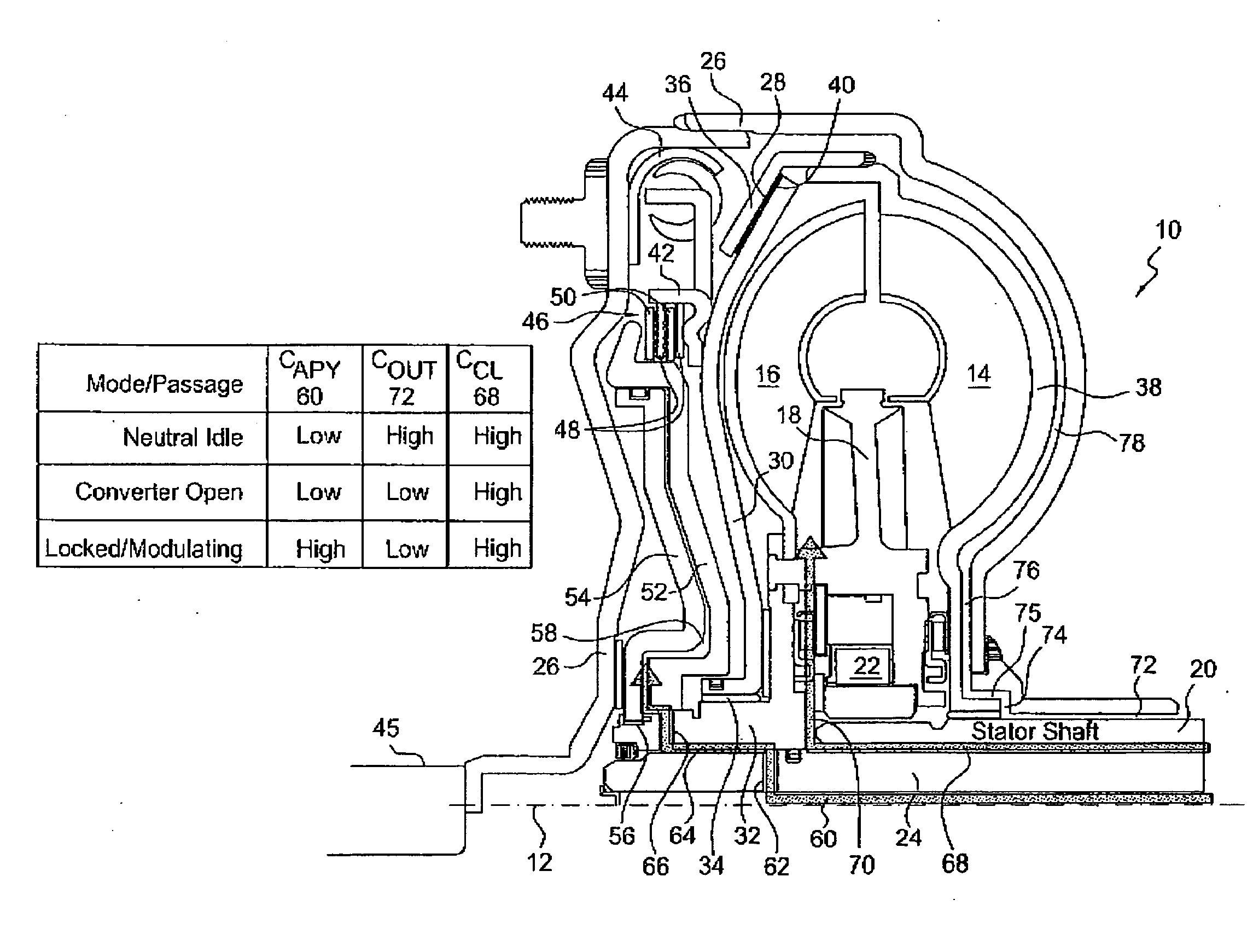
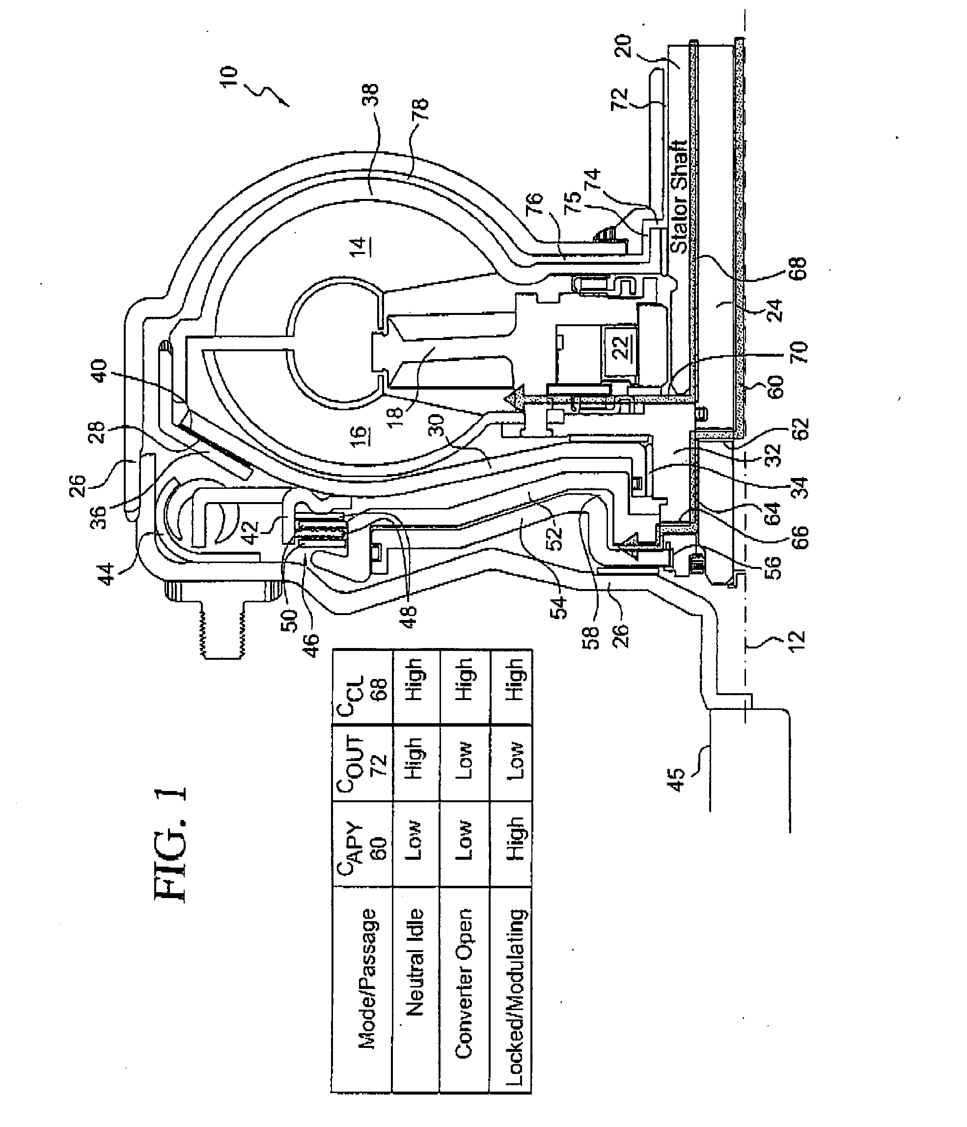
[0024]Referring now to the drawings, there is illustrated in FIG. 1 a torque converter 10, which is arranged about a central axis 12 and includes a bladed impeller 14, a bladed turbine 16, and a bladed stator 18. The impeller, stator and turbine define a toroidal fluid flow circuit, whereby the impeller is hydrokinetically connected to the turbine.

[0025]The stator 18 is secured to, and supported for rotation on a stationary stator sleeve shaft 20. An overrunning brake 22 anchors the stator to shaft 20 to prevent rotation of the stator in a direction opposite the direction of rotation of the impeller, although free-wheeling motion in the direction of rotation of the impeller is permitted. The turbine 14 is secured to a rotating transmission input shaft 24, which transmits torque to the transmission gear box (not shown). A torque converter housing 26, surrounding the turbine, impeller and stator, is driveably connected to the crankshaft of an internal combustion engine (not shown) or ...


PUM


Abstract

A system for controlling a torque converter of an automatic transmission driven by a power source, the system including a torque converter an impeller, a turbine driveably connected to a transmission input and able to be driven hydrokinetically by the impeller, a stator, an impeller clutch for alternately engaging and disengaging a drive connection between the impeller and the power source, a source of converter charge pressure communicating with the impeller clutch, a source of converter discharge pressure communicating with the impeller clutch, a magnitude of differential force due to charge pressure and discharge pressure across the impeller clutch alternately producing operating multiple operating states of the impeller clutch, and a orifice having a variable fluid flow area for changing a magnitude of converter discharge pressure.

Description

BACKGROUND OF THE INVENTION[0001]1. Field of the Invention[0002]This invention relates generally to a torque converter for an automatic transmission, and, in particular, to control of an impeller clutch among locked released and slipping states.[0003]2. Description of the Prior Art[0004]A torque converter is a modified form of a hydrodynamic fluid coupling, and like a fluid coupling, is used to transfer rotating power from a prime mover, such as an internal combustion engine or electric motor, to a rotating driven load. A torque converter is able to multiply torque when there is a substantial difference between input and output rotational speed, thus providing the equivalent of a reduction gear.[0005]In a torque converter there are at least three rotating elements: the impeller, which is mechanically driven by the prime mover; the turbine, which drives the load; and the stator, which is interposed between the impeller and turbine so that it can alter oil flow returning from the turb...

Claims


Application Information

Patent Timeline
IPC IPC(8): F16H61/38
CPCF16H45/02F16H61/62F16H2045/002F16H2045/021Y10T477/635F16H2045/0257F16H2045/0284F16H61/143F16H2045/0252
Inventor POVIRK, JACOB M.SIMPSON, WILLIAM R.
Owner FORD GLOBAL TECH LLC
Why Eureka
Try Eureka