Method for determining solenoid control current using hysteresis interpolation for transmission clutch control

a technology of transmission clutch and current determination, which is applied in the direction of instruments, mechanical devices, electromagnets with armatures, etc., can solve the problems of unfavorable clutch pressure control, and overall shift performance suffer, so as to improve control pressure, improve accuracy, and control the effect of clutch pressur

Active Publication Date: 2008-05-13
DELPHI TECH IP LTD
View PDF18 Cites 33 Cited by
  • Summary
  • Abstract
  • Description
  • Claims
  • Application Information

AI Technical Summary

Benefits of technology

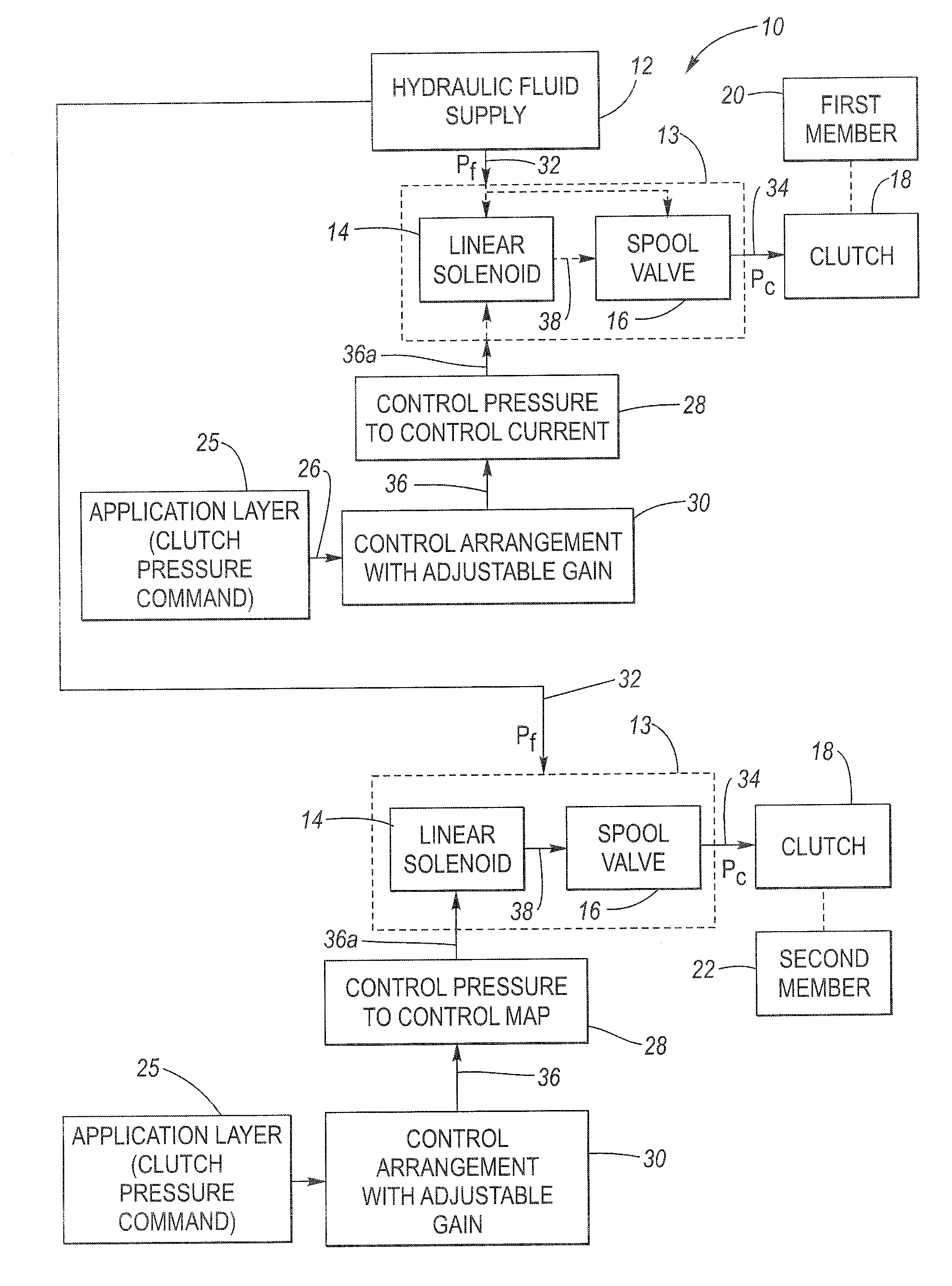
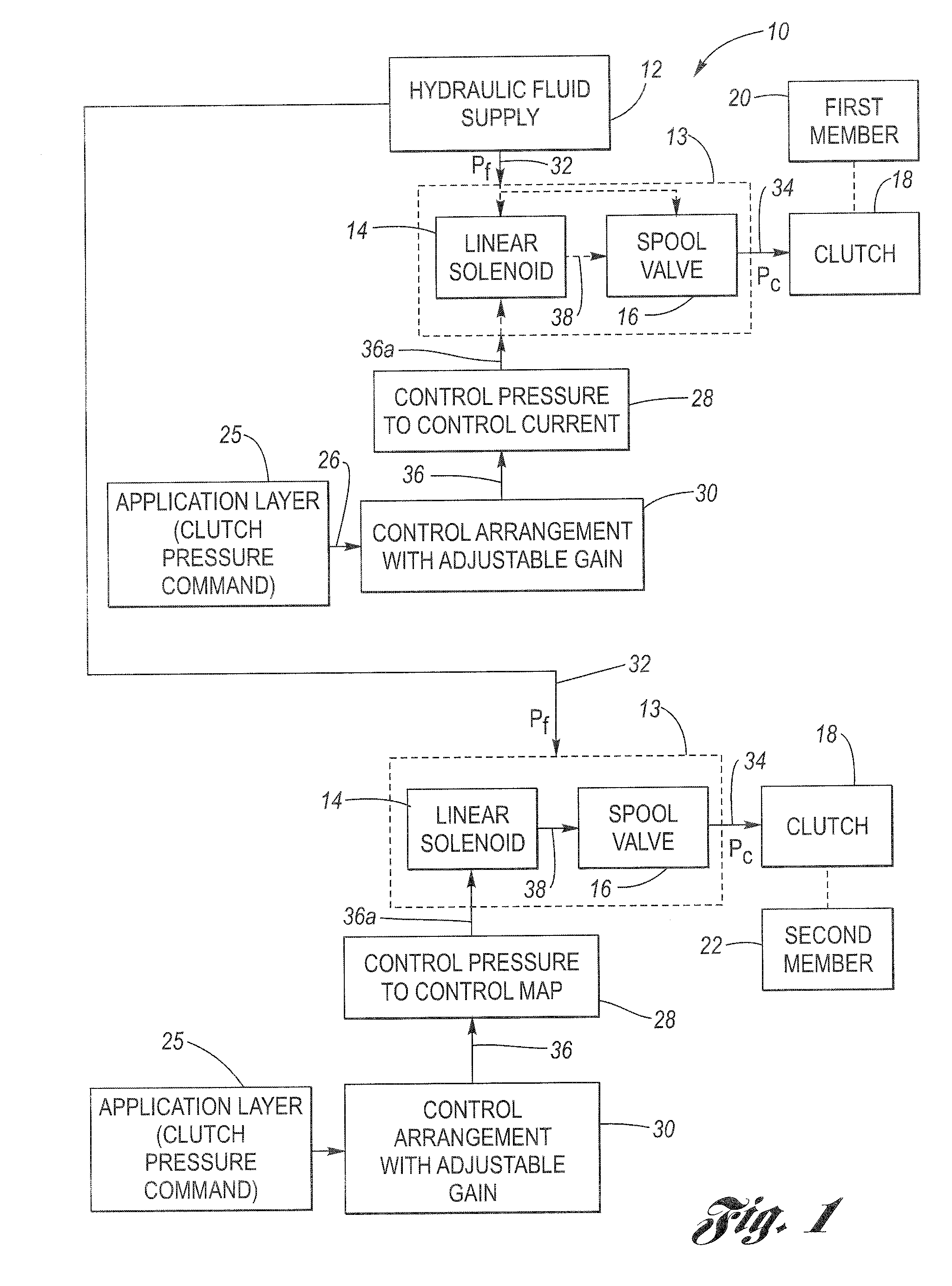
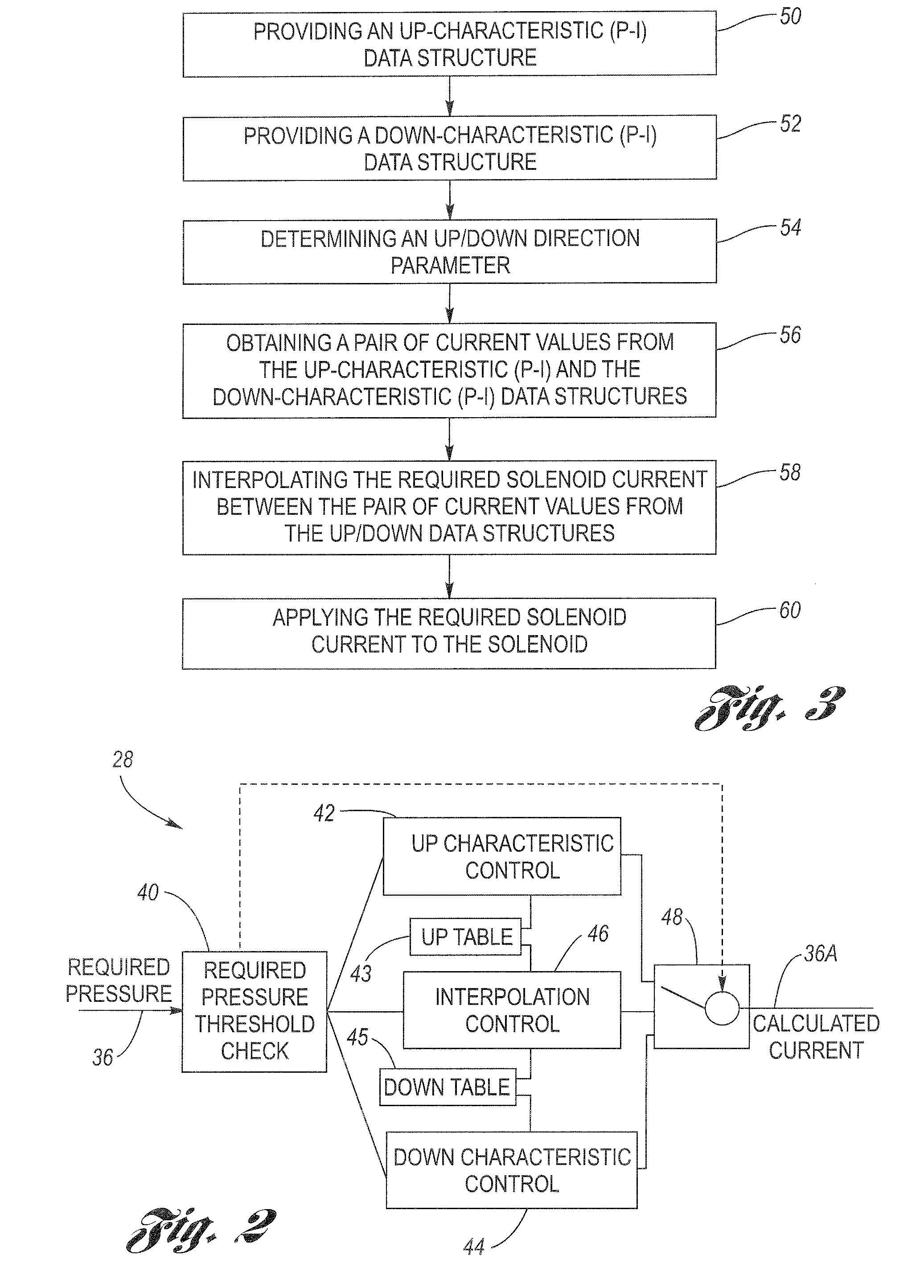
[0009]One advantage of the present invention is that it provides an improved accuracy as compared to conventional approaches. A method is provided for controlling a solenoid in a solenoid-operated electro-hydraulic pressure control module where a solenoid output pressure defines a control pressure that varies in accordance with a solenoid control current. The method includes a number of steps. The first step involves providing an up-characteristic data structure including data corresponding to an up control pressure versus solenoid control current (P-I) characteristic for increasing control pressure. The next step involves providing a down-characteristic data structure including data corresponding to a down control pressure versus solenoid control current (P-I) characteristic for a decreasing control pressure. The data structures may be embodied in up and down P-I tables.
[0010]The next step involves determining an up/down direction parameter between the present control pressure (e.g., this may be represented by the prior control pressure command) and a desired control pressure (e.g., this may be represented by a new, commanded control pressure). Next, obtaining a pair of current values from the up-characteristic data structure and the down-characteristic data structure in accordance with the commanded (desired) control pressure.
[0011]The next step involves interpolating a required solenoid control current between the pair of current values extracted from the P-I tabl

Problems solved by technology

It should be appreciated that if the timing of the engagement of one gear with the disengagement of another gear is not coordinately properly, overall shift performance may suffer.
Using the tables under

Method used


Image

  • Method for determining solenoid control current using hysteresis interpolation for transmission clutch control
  • Method for determining solenoid control current using hysteresis interpolation for transmission clutch control
  • Method for determining solenoid control current using hysteresis interpolation for transmission clutch control

Examples


example

[0053]In FIG. 4, assume that the up pressure change threshold is 100 kPa, and the requested control pressure change amounts to 60 kPa (i.e., from control pressure level 68 to level 70). The requested control pressure change will involve the up characteristic 62 (table 43) since the new, desired control pressure command is greater than the existing, previous control pressure command. Also, since the requested pressure change is less than the predetermined pressure change threshold of 100 kPa, the output of hysteresis interpolation control 46 will be used. Respective current values are taken from the up characteristic 62 (table 43) and the down characteristic 64 (table 45), based on the new, requested control pressure. The pair of current values are shown as IUP and IDN. The median value of the pair of current values is calculated, which is designated IM. A delta current value is then calculated, which in the case of FIG. 4, is evaluated by (IUP-IM). For a down pressure request, (IDN-...


PUM


Abstract

A transmission control arrangement controls the generation of a required solenoid control current that is provided to an electro-hydraulic pressure control module to ultimately control clutch pressure. The module includes a linear solenoid, which has an up direction pressure-current (P-I) data table and a down direction pressure-current (P-I) data table associated therewith. For large pressure increase change requests the up P-I table is used. For large pressure decrease change requests the down P-I table is used. An interpolation process uses current values taken from both the up and down P-I data tables for pressure change requests that are neither large increases nor large decreases. The control arrangement also includes a variable gain feature that changes the gain in dependence on the gear state of the transmission.

Description

TECHNICAL FIELD[0001]The present invention relates generally to improvements in clutch pressure controls for a vehicle automatic transmission and more particularly to a method for determining solenoid control current using hysteresis interpolation for transmission clutch pressure control.BACKGROUND OF THE INVENTION[0002]Hydraulic fluid controls can be found in a variety of automotive applications such as automatic speed change transmissions as well as others. In these applications, it is often desirable to control the pressure of the hydraulic fluid, as seen by reference to U.S. Pat. No. 6,308,725 entitled “APPARATUS FOR CONTROLLING HYDRAULIC FLUID PRESSURE” issued to Lawlyes et al., assigned to the common assignee of the present invention. Lawlyes et al. disclose a smart actuator including a solenoid element and a pressure sensor element, both of which are in electrical communication with a remote control through a wire harness. Lawlyes et al. provide for remote pressure sensing of...

Claims


Application Information

Patent Timeline
IPC IPC(8): G06F7/00
CPCF16D48/066F16H61/0251F16D2500/1026F16D2500/30806F16D2500/70217F16D2500/70223F16D2500/70605F16D2500/7061H01F7/18F16D2500/1085F16D2500/3022F16D2500/3024F16D2500/70418
Inventor HWANG, KYOUNGPILHERMAN, ANDREW D.KOZAN, MICHAEL
Owner DELPHI TECH IP LTD
Why Eureka
Try Eureka