
Indoor air humidity testing device

A technology of indoor air humidity and testing device, applied in the field of electronics, can solve problems such as energy waste and environmental pollution

Inactive Publication Date: 2012-10-31
方雪松
View PDF4 Cites 1 Cited by
  • Summary
  • Abstract
  • Description
  • Claims
  • Application Information

AI Technical Summary

Problems solved by technology

[0002] With the development of industry, environmental pollution is becoming more and more serious, and the moisture in the air is getting less and less. For this reason, many families buy air humidifiers. After the power is turned on, the air humidifiers emit water vapor into the air all the time. The moisture in the water has reached saturation, and it is constantly humidifying, unless the power supply is manually disconnected, resulting in a waste of energy

Method used


Image

  • Indoor air humidity testing device

Examples


Embodiment Construction

[0007] The present invention will be further described below in conjunction with accompanying drawing.

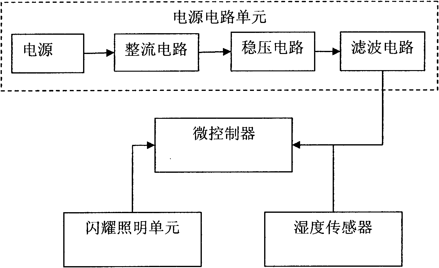
[0008] Such as figure 1 As shown, an indoor air humidity test device includes a power supply circuit unit, which is composed of a power supply, a rectifier circuit, a voltage stabilizing circuit, and a filter circuit, and also includes a microcontroller, a flashing lighting unit, a humidity sensor, and the input end of the power supply and rectification circuit Electrically connected, the output end of the rectifier circuit is electrically connected to the input end of the voltage stabilizing circuit, the output end of the filter circuit and the humidity sensor is electrically connected to the input end of the microcontroller, and the output end of the microcontroller is connected to the flashing lighting unit through the control circuit ;The shining lighting unit is LED light.

[0009] When in use, place the device anywhere in the room. When the humidity sensor senses tha...


PUM


Abstract

The invention discloses an indoor air humidity testing device, which belongs to the technical field of electronics. The indoor air humidity testing device comprises a power circuit unit, a microcontroller, a flash lighting unit and a humidity sensor, wherein the power circuit unit consists of a power source, a rectifying circuit, a voltage stabilizing circuit and a filter circuit; the power source is electrically connected with an input end of the rectifying circuit; an output end of the rectifying circuit is electrically connected with an input end of the voltage stabilizing circuit; output ends of the filter circuit and the humidity sensor are electrically connected with an input end of the microcontroller; an output end of the microcontroller is connected with the flash lighting unit through the control circuit; and the flash lighting unit is an LED (Light Emitting Diode) lamp. The indoor air humidity testing device has the beneficial effects that after the humidity sensor senses that the humidity in air reaches standard, a signal is transmitted to the microcontroller and the flash lighting unit is controlled to flash after judgment of the microcontroller, and thus, a user is reminded of turning off or turning on a switch of an air humidifier to fulfill the aim of saving power.

Description

technical field [0001] The invention relates to an indoor air testing device, in particular to a power supply protection device for an electronic circuit, and belongs to the field of electronic technology. Background technique [0002] With the development of industry, environmental pollution is becoming more and more serious, and the moisture in the air is getting less and less. For this reason, many families buy air humidifiers. After the power is turned on, the air humidifiers emit water vapor into the air all the time. The moisture in the water heater has reached saturation, and it is constantly humidified, unless the power supply is manually disconnected, resulting in a waste of energy. Contents of the invention [0003] Aiming at the above-mentioned problems in the prior art, the present invention provides an indoor air humidity testing device, which can judge whether the indoor air humidity meets the standard, thereby reminding the user to turn off or turn on the sw...

Claims


Application Information

Patent Timeline
Patent Type & Authority Applications(China)
IPC IPC(8): F24F11/02
Inventor 方雪松
Owner 方雪松
Learn More