
Voice coil motor for realizing power saving effect by utilizing magnetic conduction casing

A voice coil motor and housing technology, which is applied to electrical components, electromechanical devices, installation and other directions, can solve the problems of voice coil motor interference, complicated production of the lens carrier 45, assembly errors, etc., and achieves the effect of solving the deflection of the optical axis

Inactive Publication Date: 2010-06-16
VASSTEK INT
View PDF0 Cites 15 Cited by
  • Summary
  • Abstract
  • Description
  • Claims
  • Application Information

AI Technical Summary

Problems solved by technology

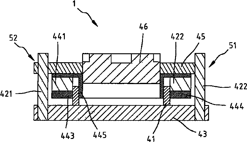
[0007] However, under the above power-saving design, the lens holder 45 must have a special open arc-shaped bearing surface 51 and a round hole 52, which makes the production of the lens holder 45 more complicated.
When the lens carrier 45 is assembled with the base 43, etc., the guide steel shaft 422 must be relative to the open arc-shaped bearing surface 51, and the guide steel shaft 421 must be relative to the through hole 52, so that the lens carrier 45 has an installation direction. At the same time, the guide steel shafts 422, 421 must pass through the open arc-shaped bearing surface 51 and the round hole 52 to be installed on the base 43 separately, which will easily lead to errors in the assembly of the guide steel shafts 422, 421, and then cause the voice coil Interference problems when the motor is activated

Method used


Image

  • Voice coil motor for realizing power saving effect by utilizing magnetic conduction casing
  • Voice coil motor for realizing power saving effect by utilizing magnetic conduction casing
  • Voice coil motor for realizing power saving effect by utilizing magnetic conduction casing

Examples


Embodiment Construction

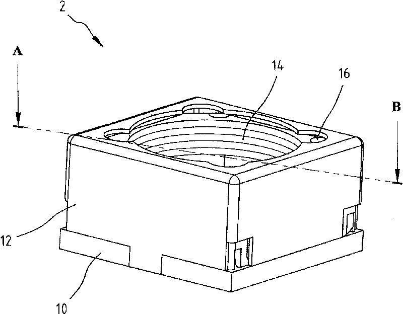
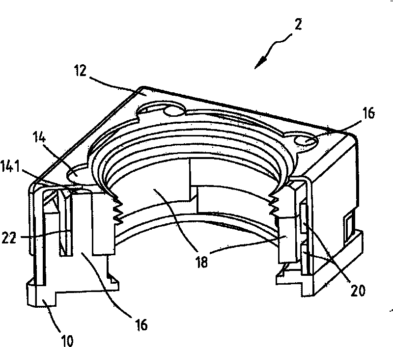
[0018] reference figure, Figure 2A-2B It is a schematic diagram of the voice coil motor of the present invention. Such as Figure 2A As shown, from the appearance, the voice coil motor 2 of the present invention includes a base 10, a housing 12 arranged on the base 10, a lens holder 14 covered by the housing 12, and a lens holder that has passed through the lens holder. 14 guide cylinder 16. along as Figure 2A The A-B line segment shown is cut, and it can be further observed that Figure 2B The three-dimensional structure diagram shown.

[0019] Such as Figure 2B As shown, the voice coil motor 2 of the present invention includes a base 10, a housing 12 disposed on the base 10, a lens mounting seat 14 covered by the housing 12, and a guide column that has passed through the lens mounting base 14. The body 16 further includes the guide cylinder 16 on the base 10 , the electromagnetic drive mechanism (mainly the coil 20 ), and the magnetically sensitive component 18 rigi...


PUM


Abstract

The invention discloses a voice coil motor for realizing the power saving effect by utilizing a magnetic conduction casing body. The voice coil motor comprises a magnetic induction component, a lens bearing seat rigidly connected with a magnetic circuit part, a base, a plurality of guide cylinder bodies fixed on the base, an electromagnetic drive mechanism and a casing covering the magnetic induction component, the lens bearing seat, the electromagnetic drive mechanism, and the like. In order to achieve the purpose of saving power, the distance between the casing and the magnetic induction component is set in a preset range, the magnetic induction component generates lateral suction to the casing, then the lens bearing seat is driven to move, thereby causing that the friction increased between the plurality of guide cylinder bodies and the hole wall of a circular hole is greater than the total weight of gravity of the magnetic induction component, the lens bearing seat and a born lens group and / or upward suction of the casing body to the magnetic induction component, and still enabling the lens group to be kept in a fixed position when the group of coil completes positioning and the power is cut off.

Description

technical field [0001] The present invention relates to a voice coil motor, in particular to a voice coil motor which utilizes a magnetically permeable housing to achieve power saving. Background technique [0002] In order to perform precise positioning control on the lens group or the magnetic head arm of the hard disk, a voice coil motor is usually used to move the lens group or the magnetic head arm of the hard disk. The mechanism of the voice coil motor is mainly to place the coil in the magnetic circuit containing the permanent magnet. [0003] In the optical system, when the current passes through the coil, the magnetic field formed by the permanent magnet will generate an interactive propulsion according to the left-hand rule, so that the holder rigidly connected with the permanent magnet is moved, and at the same time drives the lens group fixed on the holder , to achieve the purpose of optical zoom and focus. Since the moving distance of the seat is controlled by...

Claims


Application Information

Patent Timeline
IPC IPC(8): G02B7/04H02K33/18
Inventor 李世筌
Owner VASSTEK INT
Learn More