
Method and device for transmitting demodulation reference signal, as well as method and device for receiving demodulation reference signal

A technology for demodulating reference signals and sending methods, which is applied in wireless communication, network traffic/resource management, electrical components, etc., and can solve problems such as high bit error rate, data symbol and pilot symbol interference, etc.

Active Publication Date: 2012-10-31
CHINA MOBILE COMM GRP CO LTD
View PDF4 Cites 29 Cited by
  • Summary
  • Abstract
  • Description
  • Claims
  • Application Information

AI Technical Summary

Problems solved by technology

[0011] Embodiments of the present invention provide a method and device for sending demodulation reference signals, a method and device for receiving them, to solve the problem of data symbols being generated on PRBs where subcarrier offsets occur when two base stations perform cooperative transmission in the prior art Interference with pilot symbols, and the problem that the user terminal has a very high bit error rate when demodulating DM-RS

Method used


Image

  • Method and device for transmitting demodulation reference signal, as well as method and device for receiving demodulation reference signal
  • Method and device for transmitting demodulation reference signal, as well as method and device for receiving demodulation reference signal
  • Method and device for transmitting demodulation reference signal, as well as method and device for receiving demodulation reference signal

Examples


Embodiment 1

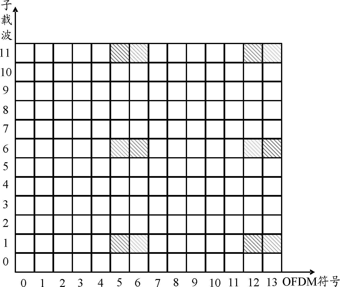
[0057] When base station 1 and base station 2 perform cooperative transmission, both base station 1 and base station 2 send DM-RS through two DM-RS ports (respectively DM-RS port 7 and DM-RS port 8), and the work of base station 1 The bandwidth is 20M, and the operating bandwidth of base station 2 is 10M. Since the DC subcarrier of base station 1 and the DC subcarrier of base station 2 are not aligned, part of the PRBs of base station 1 and base station 2 can be aligned, while the other part of the PRB is due to DC The impact of the subcarrier has a subcarrier offset in the frequency domain, such as figure 2 As shown, there are 5 PRBs in base station 1 and base station 2 that have subcarrier offsets.

[0058] Select base station 2 as the reference base station, and base station 1 as the frequency shift base station, then base station 2 is based on Figure 1A The shown DM-RS Pattern sends DM-RS, and base station 1 determines 5 PRBs with subcarrier offset in each PRB included i...

Embodiment 2

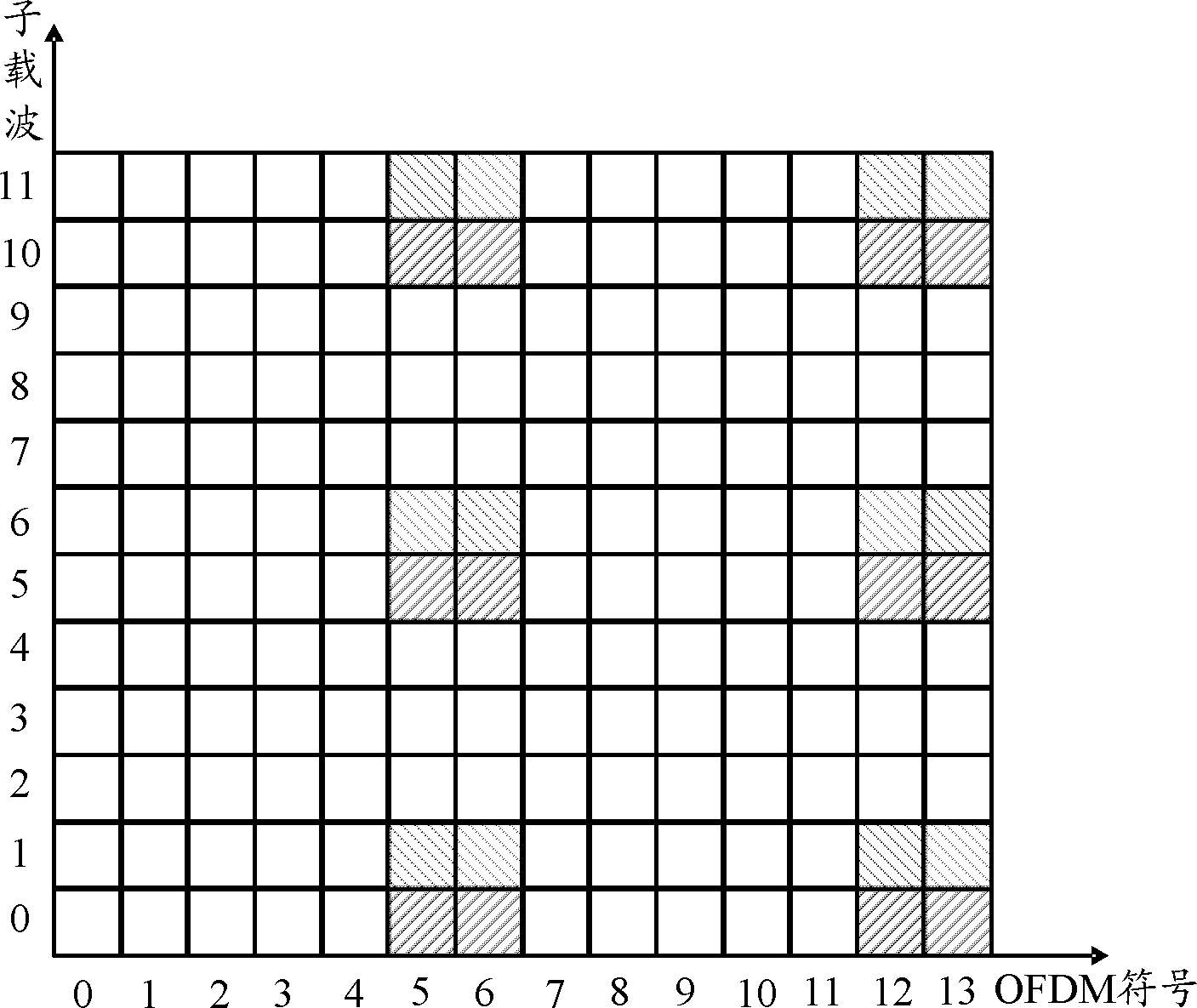
[0062] When base station 1 and base station 2 perform cooperative transmission, both base station 1 and base station 2 pass through four DM-RS ports (respectively DM-RS port 7, DM-RS port 8, DM-RS port 9 and DM-RS port 10 ) to send DM-RS, the operating bandwidth of base station 1 is 20M, and the operating bandwidth of base station 2 is 10M. Since the DC subcarrier of base station 1 and the DC subcarrier of base station 2 are not aligned, part of base station 1 and base station 2 PRBs can be aligned, while another part of PRBs is shifted by 1 subcarrier in the frequency domain due to the influence of the DC subcarrier, such as figure 2 As shown, there are 5 PRBs in base station 1 and base station 2 that have subcarrier offsets.

[0063] Select base station 2 as the reference base station, and base station 1 as the frequency shift base station, then base station 2 is based on Figure 1B The shown DM-RS Pattern sends DM-RS, and base station 1 determines 5 PRBs with subcarrier o...

Embodiment 3

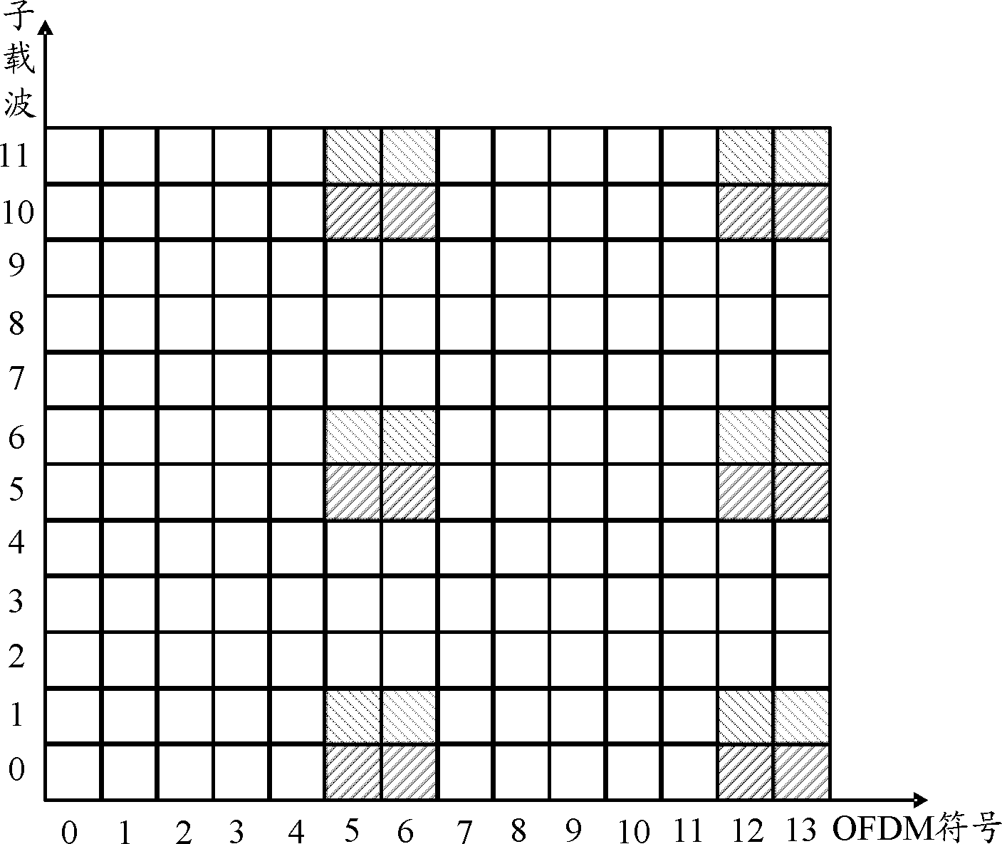
[0068] When base station 1 and base station 2 perform cooperative transmission, both base station 1 and base station 2 pass through 8 DM-RS ports (respectively DM-RS port 7, DM-RS port 8, DM-RS port 9, DM-RS port 10 , DM-RS port 11, DM-RS port 12, DM-RS port 13, DM-RS port 14) to send DM-RS, the working bandwidth of the base station 1 is 20M, and the working bandwidth of the base station 2 is 10M, because the base station The DC subcarrier of 1 and the DC subcarrier of base station 2 are not aligned, so part of the PRBs of base station 1 and base station 2 can be aligned, while the other part of the PRB has 1 subcarrier in the frequency domain due to the influence of the DC subcarrier offset, such as figure 2 As shown, there are 5 PRBs in base station 1 and base station 2 that have subcarrier offsets.

[0069] Select base station 2 as the reference base station, and base station 1 as the frequency shift base station, then base station 2 is based on Figure 1B The shown DM-R...


PUM


Abstract

The invention discloses a method and a device for transmitting a demodulation reference signal, as well as a method and a device for receiving a demodulation reference signal. The transmitting method comprises the following steps: determining a PRB (program require block) which is subjected to subcarrier migration with the PRB of a second base station among the PRB included in a sub frame to be sent of a first base station when the first base station and the second base station execute cooperative transmission; performing frequency shift on RE (receiving equipment) carried with a DM-RS (demodulation reference signal) in the direction from the DC (direct current) subcarrier of the second base station to the DC subcarrier of the first station, in the time frequency resource consisting of the determined PRB (program require block), according to the amount of the migration subcarrier of the determined PRB; in the PRB included in the sub frame, mapping the DM-RS to the RE for carrying the DM-RS; and then sending the sub frame to a user terminal. By utilizing the technical scheme, the problems in the prior art that interferences of a data symbol and a pilot symbol are likely to occur on the PRB subjected to subcarrier migration, when two base stations execute cooperative transmission, and the error code rate is very high when the user terminal demodulates the DM-RS are solved.

Description

technical field [0001] The present invention relates to the technical field of mobile communication, in particular to a method and device for sending a demodulation reference signal, and a method and device for receiving it. Background technique [0002] A Reference Signal (RS, Reference Signal) is a known signal provided by a base station and sent to a user terminal for the user terminal to perform channel estimation or channel measurement. In an Orthogonal Frequency Division Multiplexing (OFDM, Orthogonal Frequency Division Multiplexing) system, under the normal cyclic prefix (NCP, Normal Cyclic Prefix) configuration, a physical resource block (PRB, PhysicalResource Block) occupies 12 consecutive sub-blocks in the frequency domain The carrier occupies 14 consecutive OFDM symbols in the time domain. In the PRB, the RS is in the unit of resource element (RE, Resource Element). One RS occupies several REs on the PRB, and one RE is an OFDM symbol. One subcarrier on , that is,...

Claims


Application Information

Patent Timeline
Patent Type & Authority Applications(China)
IPC IPC(8): H04W28/16H04W72/04
Inventor 刘建军史志华王启星徐晓东刘光毅
Owner CHINA MOBILE COMM GRP CO LTD
Learn More