
Method for manufacturing wheel rim for vehicle

A manufacturing method and technology of rims, which are applied to rims, vehicle parts, transportation and packaging, etc., can solve problems such as difficult adoption and reduced appearance quality, and achieve the effects of reducing equipment costs, solving costs, and low total costs

Active Publication Date: 2012-10-31
TOPY INDUSTRIES
View PDF9 Cites 8 Cited by
  • Summary
  • Abstract
  • Description
  • Claims
  • Application Information

AI Technical Summary

Problems solved by technology

If a branch is set up in one vehicle rim production line, the branch is divided into three sub-lines, and one spinning equipment is installed in each sub-line, the problem of productivity is eliminated, but there are three sets of spinning equipment, and the production equipment The cost is tripled, and the installation space of the spinning equipment needs to be tripled, so it is difficult to adopt
[0012] (iii) The forming traces of the forming rollers for spinning remain on the blank, and the appearance quality is reduced

Method used


Image

  • Method for manufacturing wheel rim for vehicle
  • Method for manufacturing wheel rim for vehicle
  • Method for manufacturing wheel rim for vehicle

Examples


Embodiment 1)

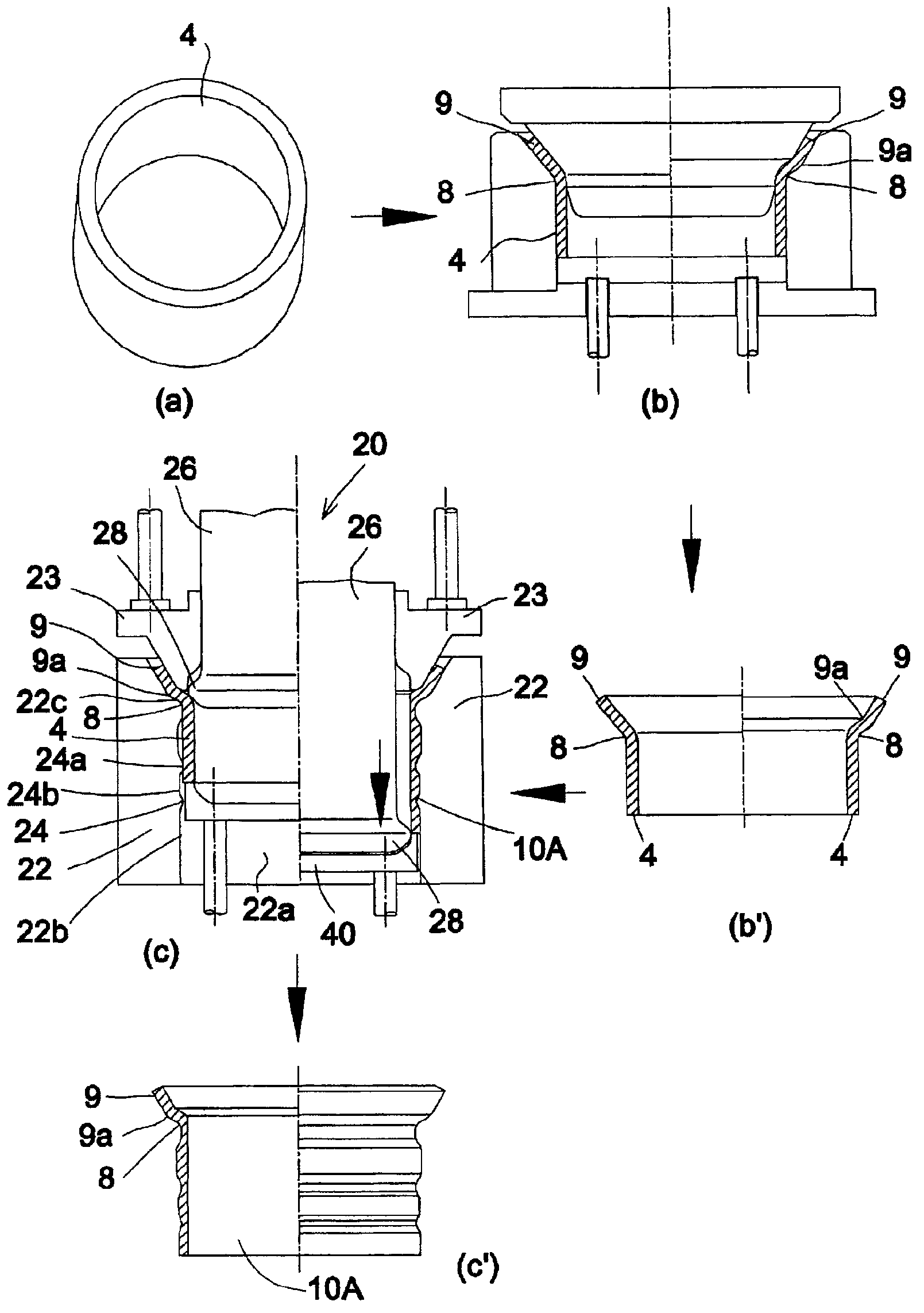
[0119] In the manufacturing method of the vehicle rim 10B according to Embodiment 1 of the present invention, as figure 1 (c), Figure 6 As shown, the die 22 is composed of an outer die having a cylindrical hole 22 a and an inner peripheral side surface 22 b , and the inner peripheral side face 22 b of the outer die is formed as a concavo-convex surface 24 . In addition, the punch 26 is constituted by an inner punch that axially enters and exits the cylindrical hole 22 a of the outer die 22 , and a protruding portion 28 is formed on an outer peripheral side surface 26 e thereof. The flange portion 9 of the cylindrical blank is bent outward in the radial direction of the cylindrical blank 4 .

[0120] Such as Figure 6 As shown, the upper end portion of the inner peripheral side surface 22b of the outer die 22 is formed with a flange receiving portion 22c for hooking and fixing the flange portion 9 of the cylindrical blank. The flange portion 9 of the cylindrical blank is br...

Embodiment 2)

[0129] In the manufacturing method of the vehicle rim 10B according to Embodiment 2 of the present invention, as Figure 11 , Figure 12 As shown, the die 22 is constituted by an inner die having an outer peripheral side surface 22e, and the outer peripheral side face 22e of the inner die 22 is formed as a concave-convex surface 24 . Moreover, the punch 26 is comprised by the outer punch which has the cylindrical hole 26a and the inner peripheral side surface 26b, and the protrusion part 28 is formed in the inner peripheral side surface 26b.

[0130] A flange receiving portion 22d for hooking and fixing the flange portion 9 of the cylindrical blank is formed on the upper end portion of the outer peripheral side surface 22e of the inner die 22 . The flange portion 9 of the cylindrical blank is brought into contact with the flange receiving portion 22d, hooked and fixed to the flange receiving portion 22d, and the cylindrical blank 4 is set on the inner die 22.

[0131] The ou...


PUM


Abstract

A method for manufacturing a wheel rim for a vehicle comprises an ironing step for ironing a tubular material (4) to manufacture a tubular member (10A) having a non-uniform thickness, the manufacture of the tubular member (10A) being performed using an ironing device (20) provided with: a punch (26); a die (22) having a side surface which faces the punch (26) and is formed as an irregular surface; and a pressing member (23). In the ironing step, a flange section (9) of the tubular material is engaged with the die (22), the pressing member (23) is moved relative to the die (22) to sandwich the flange section (9) of the tubular material under pressure between the pressing member (23) and the die (22), and then the tubular member (10A) having a non-uniform thickness is manufactured by subjecting at least a portion of the tubular material (4), the portion excluding the flange section (9) of the tubular material (4), to ironing by moving the punch (26) relative to the die (22).

Description

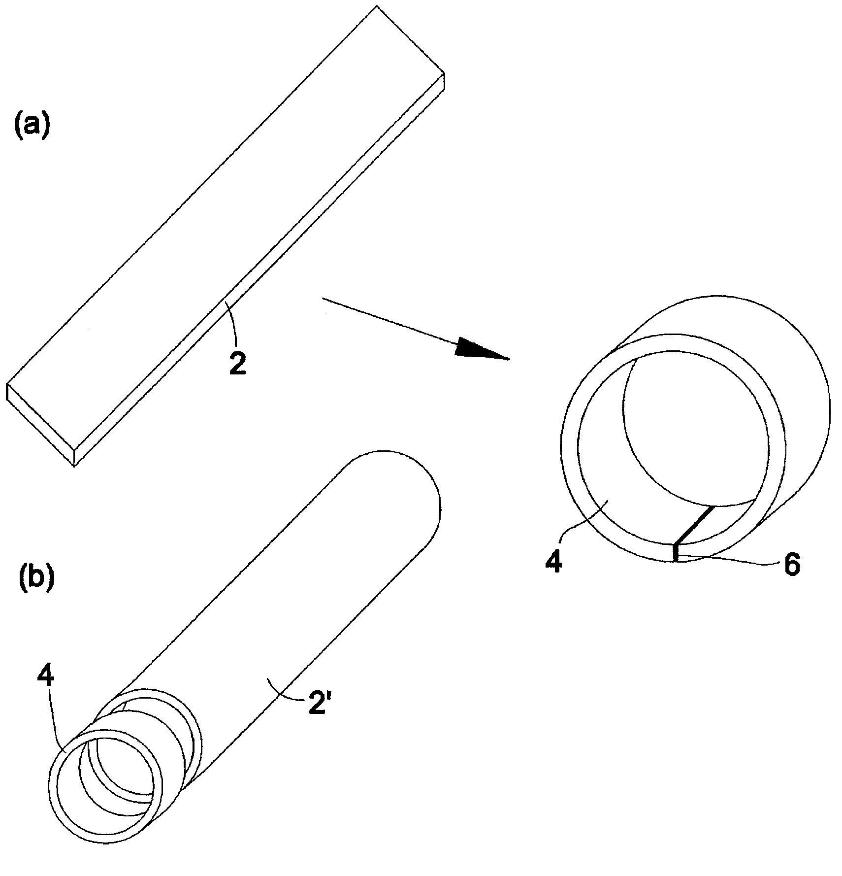
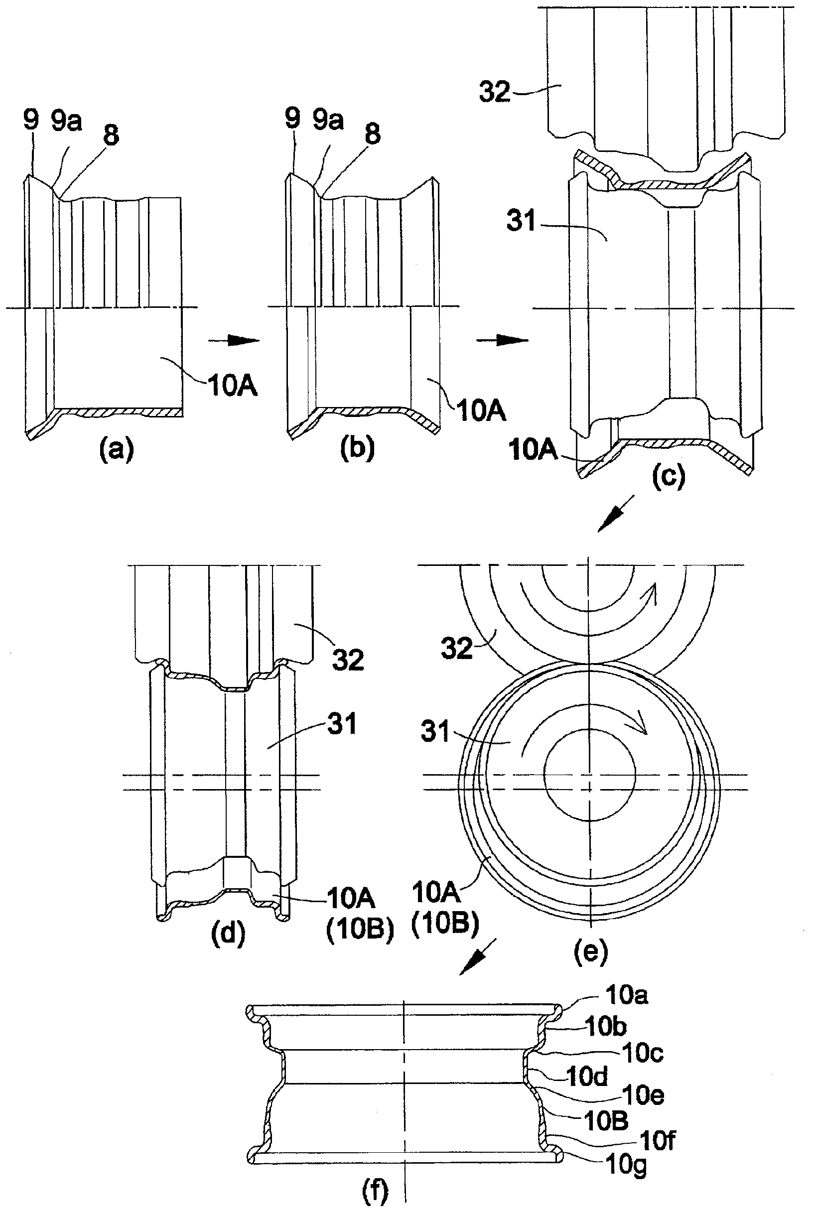
technical field [0001] The present invention relates to a method for manufacturing a vehicle rim, and in particular to a method for manufacturing a vehicle rim of unequal thickness from a cylindrical blank. Background technique [0002] In the prior art, Patent Document 1 discloses an example of a vehicle wheel rim of unequal thickness manufactured from a plate-shaped blank of constant thickness. In the method of manufacturing a vehicle rim of unequal thickness in Patent Document 1, a cylindrical blank of constant thickness is produced from a plate-shaped blank of constant thickness, and a thinning process is carried out by spinning (thinning spinning). , processing (spining), etc.) to make the cylindrical blank into a cylindrical member of unequal thickness, and roll forming the cylindrical member of unequal thickness into the shape of a vehicle rim, the manufacture varies Thickness of vehicle rims. [0003] However, the method of manufacturing a vehicle rim of unequal th...

Claims


Application Information

Patent Timeline
Patent Type & Authority Applications(China)
IPC IPC(8): B21D22/02B21D53/30
CPCB21D22/02B21D53/30B21D22/16
Inventor 阿部喜四郎高野贵光加藤胜机田口谦治
Owner TOPY INDUSTRIES
Learn More