Powder conveyer device

一种粉末输送装置、粉末的技术,应用在输送散装物料、输送机、喷射装置等方向,能够解决难正常输送、粉末滞留、不利粉末等问题,达到解决粉末流动性较差、提高粉末流动性、提高输送能力的效果

Active Publication Date: 2012-11-07
RAMSEIER KOATINGS ZHONGSHAN PAINTING EQUIP
View PDF9 Cites 22 Cited by
  • Summary
  • Abstract
  • Description
  • Claims
  • Application Information

AI Technical Summary

Problems solved by technology

[0010] 1) Both the powder inlet and the powder outlet at the bottom of the conveying chamber are located at the bottom of the powder conveying chamber, so when the powder is sucked, the powder will be blocked by the powder that has entered the conveying chamber before, which is not conducive to absorbing more powder into the conveying chamber, that is The existing powder inlet has the problem of unsmooth powder feeding;
[0011] 2) The original design tends to cause some powder with poor flow properties to stay in the bottom area of ​​the conveying chamber, making it difficult to transport normally and easily blocking the powder outlet channel;
[0012] 3) When the original powder pump is delivering powder, the air flow is controlled intermittently or continuously, which will be affected by the intermittent work of the powder suction plunger of the powder pump and become discontinuous powder delivery, resulting in uneven powder delivery. question

Method used


Image

  • Powder conveyer device
  • Powder conveyer device
  • Powder conveyer device

Examples


Embodiment 1

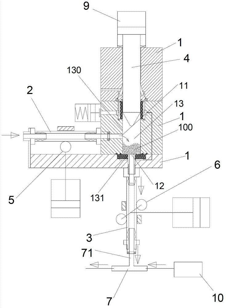
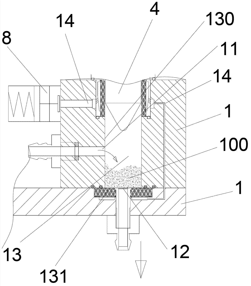
[0045]Embodiment one: if figure 1 , figure 2 , image 3 As shown, a powder conveying device includes a pump body 1, a powder suction plunger 4, a powder suction pipe 2, a powder discharge pipe 3, a powder suction pipe switch valve 5 and a powder discharge pipe switch valve 6, wherein the pump body 1 is provided with Transmission cavity 13, the powder inlet 11 is set on the transmission cavity 13 to connect with the powder suction pipe 2, the powder discharge port 12 is set on the transmission cavity 13 to connect with one end of the powder discharge tube 3; the powder suction plunger 4 is installed in the transmission cavity 13, It can move up and down along the conveying chamber 13. When the powder suction plunger 4 goes up, the powder suction pipe switch valve 5 opens the powder suction pipe 2, the powder discharge pipe switch valve 6 closes the powder discharge pipe 3, and the powder 100 is sucked and conveyed from the powder suction pipe 2 Cavity 13; when the powder suc...

Embodiment 2

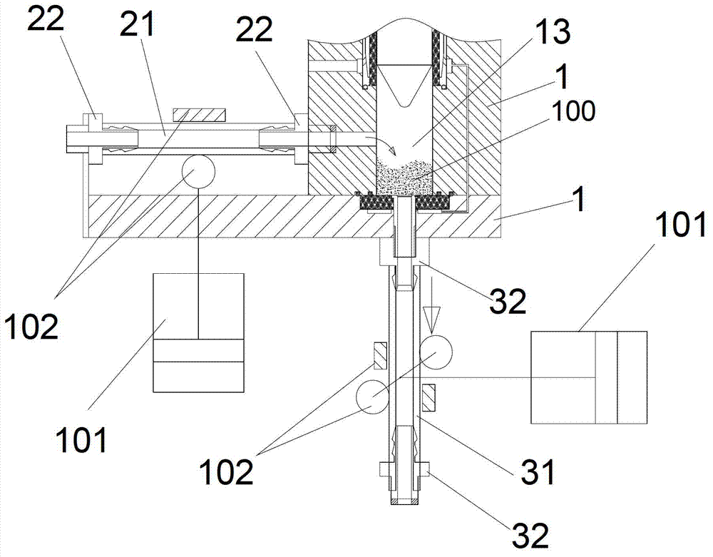
[0048] Embodiment two: if Figure 4 As shown, a powder conveying device, the pump body 1 is provided with a left conveying chamber 13a and a right conveying chamber 13b, and the left powder suction plunger 4a and the right powder suction plunger 4b are respectively installed in the left conveying chamber 13a and the right conveying chamber 13b The left powder inlet 11a is connected to the left powder suction pipe (not shown in the figure) on the left transmission chamber 11a, and the left powder outlet 12a is connected to one end of the left powder outlet pipe 3a on the left transmission chamber 1a; The right powder inlet 11b is arranged on 11b to be connected with the right powder suction pipe (not shown in the figure), and the right powder outlet 12b is arranged on the right delivery chamber 1b to be connected with one end of the right powder outlet pipe 3b; The powder pipe switch valve is controlled, the right powder suction pipe is controlled by the right powder suction pi...


PUM


Abstract

The invention relates to a powder conveyer device. The powder conveyer device comprises a pump body, a powder absorption plunger, a powder absorption pipe, a powder discharge pipe, a powder absorption pipe switch valve and a powder discharge pipe switch valve, wherein the pump body is internally provided with a conveying cavity; the conveying cavity is provided with a powder inlet connected with the powder absorption pipe; the conveying cavity is provided with a powder outlet connected with one end of the powder discharge pipe; the powder absorption plunger is arranged inside the conveying cavity and can slide up and down along the conveying cavity; when the powder absorption plunger moves upwards, the powder absorption pipe switch valve opens the powder absorption pipe, the powder discharge pipe switch valve closes the powder discharge pipe, and powders are sucked into the conveying cavity from the powder absorption pipe; when the powder absorption plunger moves downwards, the powder absorption pipe switch valve closes the powder absorption pipe, the powder discharge pipe switch valve opens the powder discharge pipe, and the powders are discharged through the powder discharge pipe from the conveying cavity; the powder inlet is placed on the inner side wall of the conveying cavity; and the powder inlet is higher than the powder outlet. The powders are more smoothly fed into the powder conveyer device when the powder conveyer device feeds with the powders, so that the powder feeding quantity and the powder feeding stationarity can be improved. As the powder discharge pipe switch valve can perform superposed powder discharge, the waving of the discharged powders is eliminated, and the stationarity and the stability of the discharged powders can be improved.

Description

1. Technical field [0001] The invention relates to a powder conveying device, which is mainly used for conveying solid powder medium. 2. Background technology [0002] Currently known powder conveying devices operate according to the Venturi principle, in which the powder is carried by a gas flow. Such devices are simple in structure, but they have the following three drawbacks. Firstly, the achievable powder concentration in the gas flow is very low and the powder is transported by gas entrainment, i.e. the carrier gas velocity must be greater than the minimum hover velocity of the powder. Second, the consistency of the amount of powder delivered can fluctuate over time. In addition, it is difficult to accurately adjust the amount of powder. These deficiencies are exacerbated when Venturi pumps deliver powder coatings, as the final powder coating can fluctuate significantly over time in terms of film thickness and visual quality. [0003] Consequently, transport solutio...

Claims


Application Information

Patent Timeline
Patent Type & Authority Applications(China)
IPC IPC(8): B65G53/14B65G53/34B65G53/46
CPCB65G53/14B05B7/1459B65G53/16B65G53/40F04B15/00F04B19/22
Inventor 高敏坚柯儒群
Owner RAMSEIER KOATINGS ZHONGSHAN PAINTING EQUIP
Why Eureka
Try Eureka