Backlight module and LCD including same

A technology of liquid crystal display and backlight module, which is applied in the direction of optics, instruments, electric light sources, etc. It can solve the problems of narrowing the frame of the module, disadvantages, uneven brightness and darkness of the module screen, and achieve the effect of improving the positioning strength

Inactive Publication Date: 2012-11-07
TCL CHINA STAR OPTOELECTRONICS TECH CO LTD
View PDF5 Cites 5 Cited by
  • Summary
  • Abstract
  • Description
  • Claims
  • Application Information

AI Technical Summary

Problems solved by technology

[0004] like figure 2 As shown, because the round steel column 103 is in point contact with other parts such as the optical plate 102, when the vibration impacts, the contact surface between the optical plate 102 and the round steel column 103 is extremely small, due to the reaction force of the round steel column 103, this When the optical plate 102 will bear the maximum pressure, that is, stress concentration, the optical plate 102 will be deformed or even ruptured (such as figure 2 shown by the wavy line); as image 3 As shown, the optical film 101 is suspended by a round steel column 103, and the contact surface is also a point contact. Since the optical film 101 is suspended, and the optical film 101 is a sheet film, when the sheet film is stressed at one point, it will Under the action of gravity, with the force point as the center point, two angular components are generated (such as image 3 As shown by the arrow symbol), that is, the sheet film cannot be placed in balance when there is only one fulcrum, so it will cause hanging warping and deformation, resulting in uneven brightness and darkness of the module picture
[0005] In addition, since the riveted round steel column 103 is used, in order to obtain higher strength, the round steel column 103 should not be too small, and at the same time, it is necessary to provide enough space for placing the bottom of the round steel column 103 and the riveting stamping space, which is not conducive to reducing the frame of the module

Method used


Image

  • Backlight module and LCD including same
  • Backlight module and LCD including same
  • Backlight module and LCD including same

Examples


Embodiment Construction

[0025] Further details will be given below in conjunction with the preferred embodiment shown in the accompanying drawings.

[0026] see Figure 4 and Figure 5 , Figure 4 A schematic diagram of a liquid crystal display using a backlight module with a stand according to an embodiment of the present invention; Figure 5 for Figure 4 A schematic diagram of the bracket used by the backlight module.

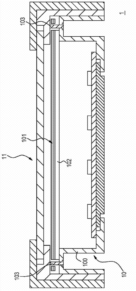
[0027] Such as Figure 4 As shown, the liquid crystal display 2 includes a backlight module 20 and a liquid crystal display panel 21 disposed beside the backlight module 20 . The backlight module 20 includes a backplane 200 . The backplane 200 has at least one side. In this embodiment, the at least one side is illustrated by the fact that the backplane 200 has a first side 200 a and a second side 200 b, but it is not limited thereto.

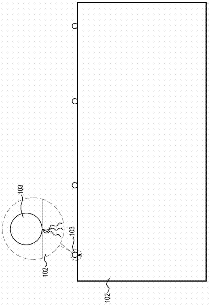
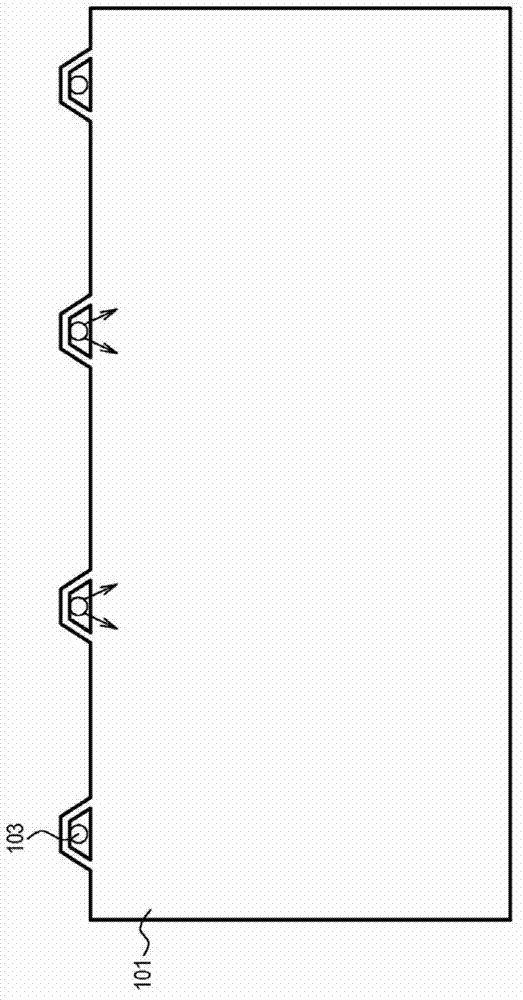
[0028] The backlight module 20 has a backlight unit 201 , and the backlight unit 201 includes an optical plate 202 and an optical film 203 ....


PUM


Abstract

A backlight module includes a back panel provided with at least one side, and is provided with a backlight unit including an optical plate and an optical film, wherein the at least one side is provided with a surface. The backlight module is characterized in that the surfaces are equipped with brackets; the brackets include horizontal parts and vertical parts extending from the horizontal parts; the vertical parts include planes and convexes; the planes are used for supporting the optical plate; and the convexes are used for positioning the optical film. The invention further provides an LCD including the backlight module.

Description

technical field [0001] The invention relates to a backlight module, in particular to a backlight module and a liquid crystal display which use the plane of the bracket to support the optical plate and the projections of the bracket to position the optical film. Background technique [0002] see Figure 1 to Figure 3 , figure 1 It is a schematic diagram of an existing liquid crystal display; figure 2 for figure 1 A schematic diagram of the deformation or rupture of the optical plate caused by the force on the round steel column of the backlight module of the liquid crystal display; image 3 for figure 1 A schematic diagram of the point contact between the optical film of the backlight module of the liquid crystal display and the round steel column. [0003] Such as figure 1 As shown, the liquid crystal display 1 includes a backlight module 10 and a liquid crystal display panel 11 . The backplane structure 100 of the backlight module 10 often adopts n-type bending t...

Claims


Application Information

Patent Timeline
Patent Type & Authority Applications(China)
IPC IPC(8): F21S8/00F21V17/12G02F1/13357
CPCG02F1/1333G02F1/133608G02F2201/54
Inventor 唐国富
Owner TCL CHINA STAR OPTOELECTRONICS TECH CO LTD
Why Eureka
Try Eureka