Controllable heat exchanger for a motor vehicle air conditioning system

A technology for heat exchangers and automotive air conditioners, which is applied to heat exchange equipment, indirect heat exchangers, heat exchanger types, etc., and can solve the problems of air conditioning equipment efficiency and adverse effects on power.

Inactive Publication Date: 2012-11-07
GM GLOBAL TECH OPERATIONS LLC
View PDF1 Cites 7 Cited by
  • Summary
  • Abstract
  • Description
  • Claims
  • Application Information

AI Technical Summary

Problems solved by technology

However, this power limitation on the built-in heat exchanger may have an adverse effect on the efficiency and power of the air conditioner during normal operation

Method used


Image

  • Controllable heat exchanger for a motor vehicle air conditioning system
  • Controllable heat exchanger for a motor vehicle air conditioning system
  • Controllable heat exchanger for a motor vehicle air conditioning system

Examples


Embodiment Construction

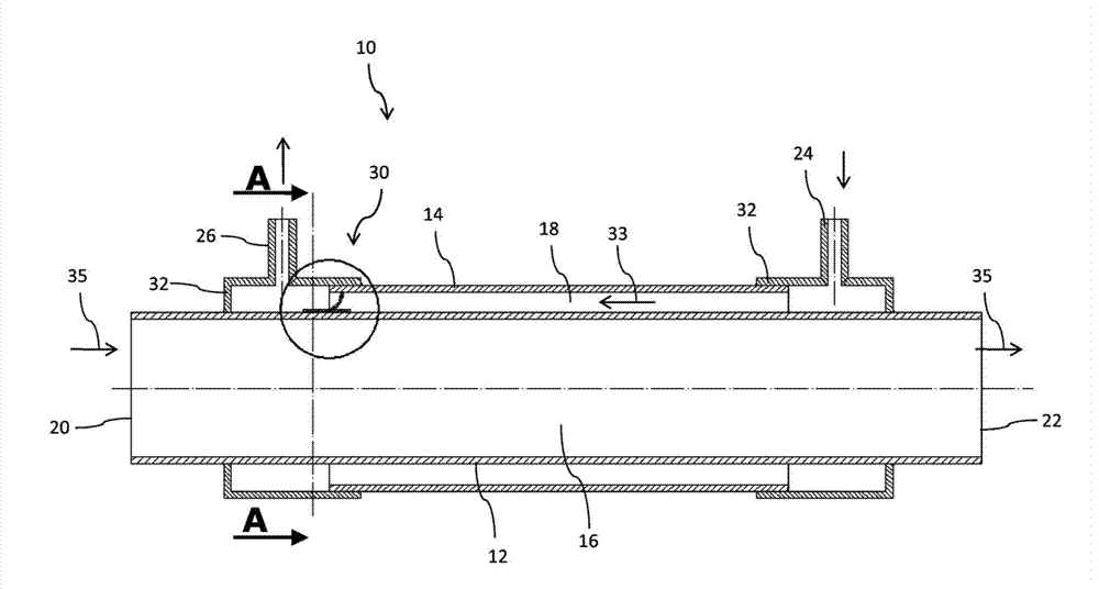
[0039] exist figure 1 The tubular heat exchanger 10 schematically sketched in , inside an air-conditioning system and adjustable in terms of its heat exchange capacity has an inner tube 12 and an outer tube 14 arranged concentrically to the inner tube 12 . A gap 18 through which the heat exchanger medium can flow is formed between the inner tube 12 and the outer tube 14 .

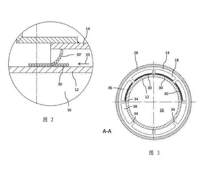
[0040] In addition to combining image 3 As can be seen in the cross-section in , the gap 18 is divided into individual channels 36 , 38 , at least some of which are equipped with adjustment elements 30 . Therefore according to image 3 The cross-section of FIG. 2 shows a total of eight channels 36 , 38 each extending in the longitudinal direction of the tube, which channels 36 , 38 form the gap 18 between the inner tube 12 and the outer tube 14 . Here, only in the image 3 The upper four channels 36 are equipped with adjusting elements 30 , while the lower channels 38 are permanently and temperature-in...


PUM


Abstract

A heat exchanger for a motor vehicle air conditioning system is provided. The heat exchanger includes an inner tube through which a heat exchanger medium can flow, an outer tube that at least regionally envelops the inner tube forming an intermediate space, and a regulating unit fluidically connected to the intermediate space. The regulating unit is configured to alter the flow resistance of the intermediate space as a function of the temperature of a heat exchanger medium that flows through the intermediate space.

Description

technical field [0001] The invention relates to a heat exchanger or heat exchanger for a vehicle air-conditioning system, which is designed in particular to exchange heat energy in a coolant circuit. Background technique [0002] Air-conditioning unit built-in heat exchangers, so-called built-in heat exchangers (IHX), are known for increasing the power and efficiency of automotive air-conditioning units, which connect the section of the coolant circuit between the evaporator and the compressor with the condensing The coolant circuit section between the regulator and the pressure reducing valve is thermally coupled. The relatively cold coolant flowing from the evaporator to the compressor can in this way be used for (pre)cooling or recooling the relatively hot coolant flowing into the pressure reducing device arranged on the high-pressure side of the coolant circuit. [0003] DE 10 2005 052 972 A1 thus describes, for example, a double-walled heat exchanger tube having an out...

Claims


Application Information

Patent Timeline
Patent Type & Authority Applications(China)
IPC IPC(8): F28F27/00F28D7/10F28F13/08
CPCF25B40/00F28F27/02F25B2600/2515B60H1/00342F28D2021/0068F28D7/106F28F2255/04B60H1/00321F28D7/10F28F27/00
Inventor L.西博尔德A.瑟伊
Owner GM GLOBAL TECH OPERATIONS LLC
Why Eureka
Try Eureka