Clip-on touch-sensitive device for display device

A technology for touch sensing and display equipment, which is applied to computer monitor casings, input/output processes of data processing, instruments, etc., and can solve problems such as expensive

Inactive Publication Date: 2012-11-07
THALES SA
View PDF5 Cites 0 Cited by
  • Summary
  • Abstract
  • Description
  • Claims
  • Application Information

AI Technical Summary

Problems solved by technology

This solution is very expensive as it requires a full update of the d

Method used


Image

  • Clip-on touch-sensitive device for display device
  • Clip-on touch-sensitive device for display device
  • Clip-on touch-sensitive device for display device

Examples


Embodiment Construction

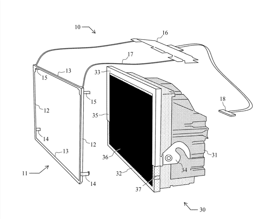
[0017] By way of non-limiting example, figure 1 A perspective view of the touch sensing device 10 and associated display device 30 according to the present invention is shown prior to the fastening detection frame.

[0018] In the present case, the touch-sensitive device 10 operates by optical detection. Other detection techniques, such as electronic detection, are compatible with the present invention.

[0019] Touch-sensing devices include:

[0020] - a touch-sensitive screen 11 in the form of a substantially rectangular frame, and the touch-sensitive screen comprises:

[0021] two side members 12 and two cross members 13;

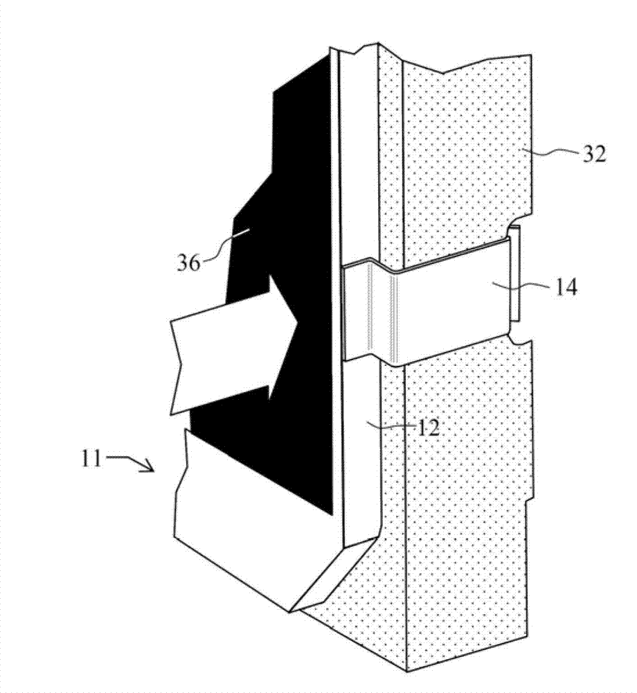
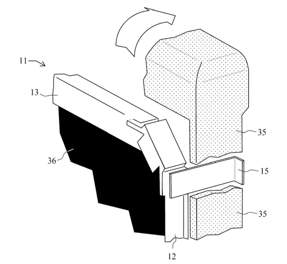
[0022] Two fastening clips 14 and two securing clips 15 are secured to the side member 12 .

[0023] figure 1 In the case of , the fastening clip is located on the bottom of the side member and the retaining clip is located on the top of the side arm. This arrangement can be modified to suit other types of displays;

[0024] a light emitter and tw...


PUM


Abstract

The invention relates to a clip-on touch-sensitive device for a display device. The general field of the invention is that of touch-sensitive devices (10) which are connectable to a display device (30) of the aeronautical type including at least a front face (32), a rear face and a locking handle (33) situated on the front face and comprise a touch-sensitive screen (11). The touch-sensitive screen (11) according to the invention at least comprises two fastening clips (14) and two retaining clips (15) fixed onto its members (12). All the four clips ensure the fastening of the touch-sensitive screen on the front face of the display device when the locking handle is in the locked position. The retaining clips (15) are locked by the lateral arms of said locking handle.

Description

technical field [0001] The field of the invention is touch sensitive screens mounted on display devices. The primary application involves displays for aircraft instrument panels. Background technique [0002] There are different human-machine interfaces for monitoring, modifying or controlling the display of a display device. For several years, and especially in the IT or telephony public domain, touch-sensitive screens have been used to implement these interfaces, the user modifying the data of the display system directly with his hand or through a stylus. [0003] Different technical principles are used to produce touch-sensitive screens. Electronic principles can be used to locally modify electrical parameters (such as resistance or capacitance) close to objects on the screen. Optical devices can also be used based on the use of light sources and miniature cameras that capture images of objects in the vicinity of the screen and determine the location of the objects by ...

Claims


Application Information

Patent Timeline
IPC IPC(8): G06F3/041B64D43/00
CPCG06F3/041G06F1/1607G06F3/0421G06F3/0428
Inventor J-M·古瓦D·拉雷
Owner THALES SA
Why Eureka
Try Eureka