
Method and system for locating a bacterial colony on a culture plate

Pending Publication Date: 2022-10-13
BD KIESTRA BV
View PDF0 Cites 0 Cited by
  • Summary
  • Abstract
  • Description
  • Claims
  • Application Information

AI Technical Summary

Benefits of technology

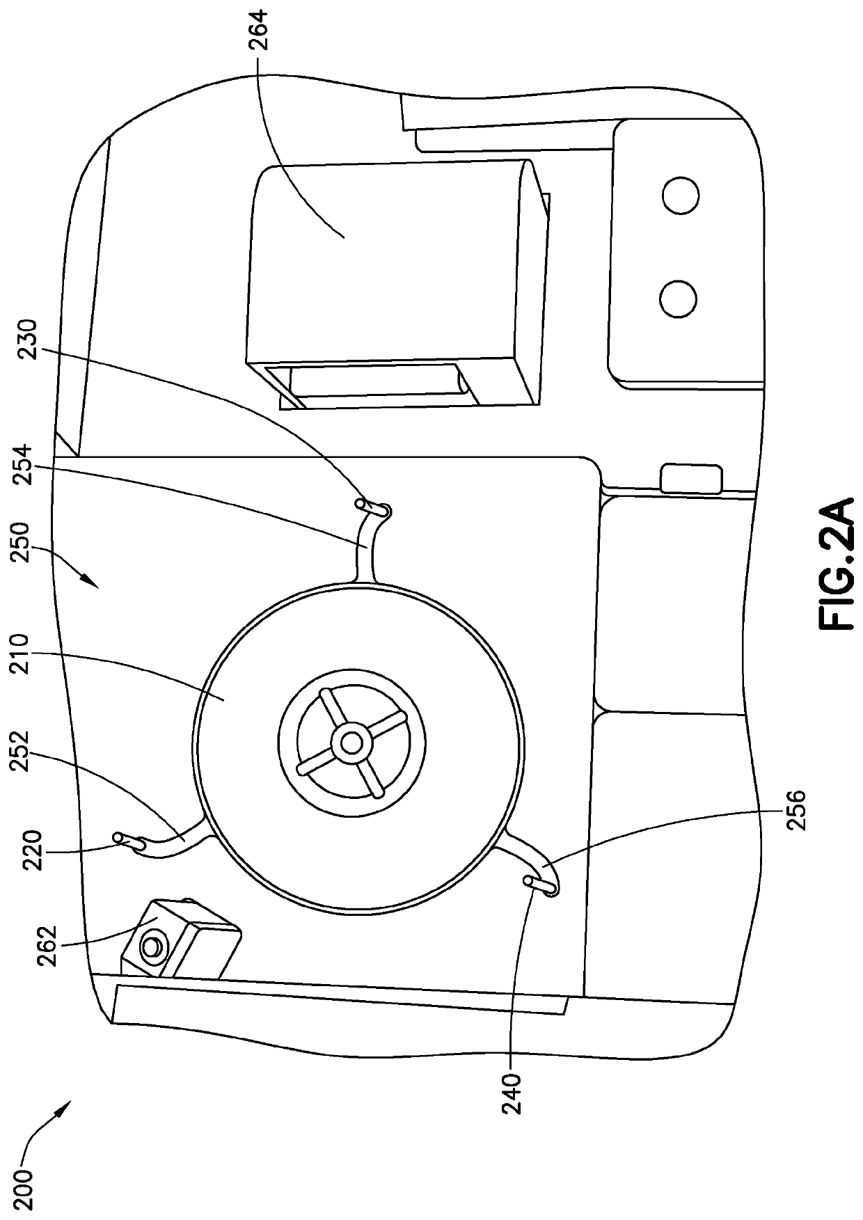
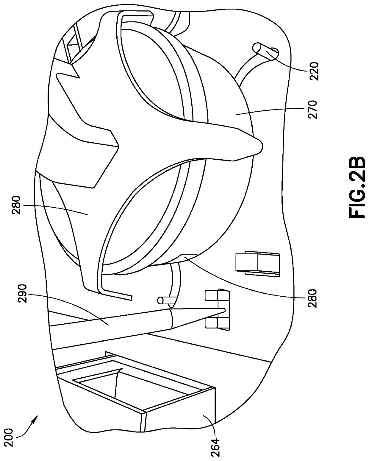
The patent describes an apparatus and method for identifying and locating colonies of microorganisms on a culture plate. The apparatus uses a simple mechanical arrangement to allow users to manually mark the location of the colonies or to use a webcam to capture the coordinates of the colonies. The apparatus applies barcodes to the plate and uses a laser pointer or cursor to mark the coordinates. The apparatus is tolerant to small variations in the placement of the colony pick tool, with a tolerance of ±1 mm. The apparatus can be used in a variety of settings and with different types of culture plates. The method involves placing the culture dish on a table, capturing an image of the dish, and dispensing a label onto the dish. The label dispenser has a wheel mount and a tensioning roller that subjects the label to tension. The apparatus and method provide a convenient and efficient way to identify and locate colonies on culture plates.

Problems solved by technology

However, such an apparatus requires determining colony coordinates from an image of the culture plate.

Method used


Image

  • Method and system for locating a bacterial colony on a culture plate
  • Method and system for locating a bacterial colony on a culture plate
  • Method and system for locating a bacterial colony on a culture plate

Examples


first embodiment

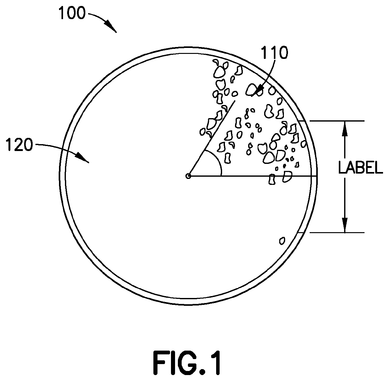
[0039]In the first embodiment, the colony locations can be marked using a laser pointing device directed either at the surface of the culture dish or an image of the culture dish. One example of how a laser pointing device might be used to locate colonies is described in detail below.

second embodiment

[0040]In a second embodiment, a view finder with crosshairs (i.e. a pair of fine wires or lines crossing at right angles in the focal plane) is used to assign the colony coordinates relative to the fiducials. This embodiment is illustrated in FIG. 14. In this embodiment, the view finder is used with an angled mirror (about forty-five (45) degrees in one embodiment) so that the user can look into the view-finder in a direction that is approximately parallel to the surface on which the colonies are located. The angled mirror re-orients the user's field of view approximately ninety (90) degrees so that the user can look into the viewfinder in an approximately horizontal direction and view the surface on which the colonies are located from a vertical perspective. As described in further detail below, the view finder is used to allow a user to manually view a colony and register its coordinates with reference to the plate center and label center fiducials. Registration of such coordinate...


PUM

PropertyMeasurementUnit
diameteraaaaaaaaaa
field of viewaaaaaaaaaa
tensionaaaaaaaaaa

Abstract

An apparatus that configures a culture plate for precisely assigning coordinates to a selected colony by assigning fiducials to the culture plate using simple mechanical techniques. The fiducials correspond to the plate center and the center of a barcode label applied to the side of the culture plate by the apparatus. The apparatus then deploys mechanisms to apply coordinates to colonies identified by the user relative to the fiducials. One such mechanism is a webcam pointed at the culture plate that allows a technician to mark the colonies on a display using a computer mouse or equivalent cursor. Another mechanism deploys a laser pointer directed at the colony wherein the apparatus assigns coordinates to the location of the colony onto which the laser pointer is directed. In a third mechanism, the user views the surface of the culture plate through a viewfinder and manually registers coordinates when the view finder cross hairs are over a target colony. The selected colonies are assigned precise coordinates with reference to the two fiducials. Software is provided such that pixels in the image of the culture plate correspond to the coordinates of the culture dish relative to the fiducials.

Description

CROSS-REFERENCE TO RELATED APPLICATION[0001]This application claims the benefit of the U.S. Provisional Application No. 62 / 867,560, which was filed on Jun. 27, 2019 and is incorporated herein by reference.BACKGROUND OF THE INVENTION[0002]Products and samples are routinely tested for microbial contamination for a variety of reasons from determining if a patient is infected with a microorganism to determining whether food is contaminated with microorganisms. Because such testing is ubiquitous, large scale laboratories have been developed that can test hundreds or thousands of such samples. In order to provide laboratories with high throughput and lower overhead, these laboratories are becoming highly automated, to reduce the number of technicians needed to run such tests. One such automated platform is described in WO / 2016 / 191646 entitled “Automated Method and System for Obtaining and Preparing Microorganism Sample for Both Identification and Antibiotic Susceptibility Tests” was publi...

Claims


Application Information

Patent Timeline
Patent Type & Authority Applications(United States)
IPC IPC(8): C12M1/34C12M3/00
CPCC12M41/36C12M23/48C12M33/02C12M33/18C12M41/48C12M23/00C12Q1/04
Inventor MARCELPOIL, RAPHAEL RODOLPHEKLEEFSTRA, MARTIJNFEIJEN, FRANCISCUSVOLLE, JEAN-MARCOKKEMA-VAN DER LEI, MARISKAMULDER, GERARDVEENINGA, EELKE JOHANNES
Owner BD KIESTRA BV
Learn More