Anti-floating structure of shallow-buried shield tunnel

A shield method and tunnel technology, applied in tunnels, infrastructure engineering, protection devices, etc., can solve problems such as practical limitations, and achieve the effect of good waterproof ability and good overall anti-floating effect.

Active Publication Date: 2014-05-14
SHANGHAI URBAN CONSTR DESIGN RES INST GRP CO LTD +1
View PDF4 Cites 3 Cited by
  • Summary
  • Abstract
  • Description
  • Claims
  • Application Information

AI Technical Summary

Problems solved by technology

When there are no uplift pile construction conditions around the existing tunnel or the tunnel is a new shallow b...

Method used


Image

  • Anti-floating structure of shallow-buried shield tunnel
  • Anti-floating structure of shallow-buried shield tunnel
  • Anti-floating structure of shallow-buried shield tunnel

Examples


Embodiment Construction

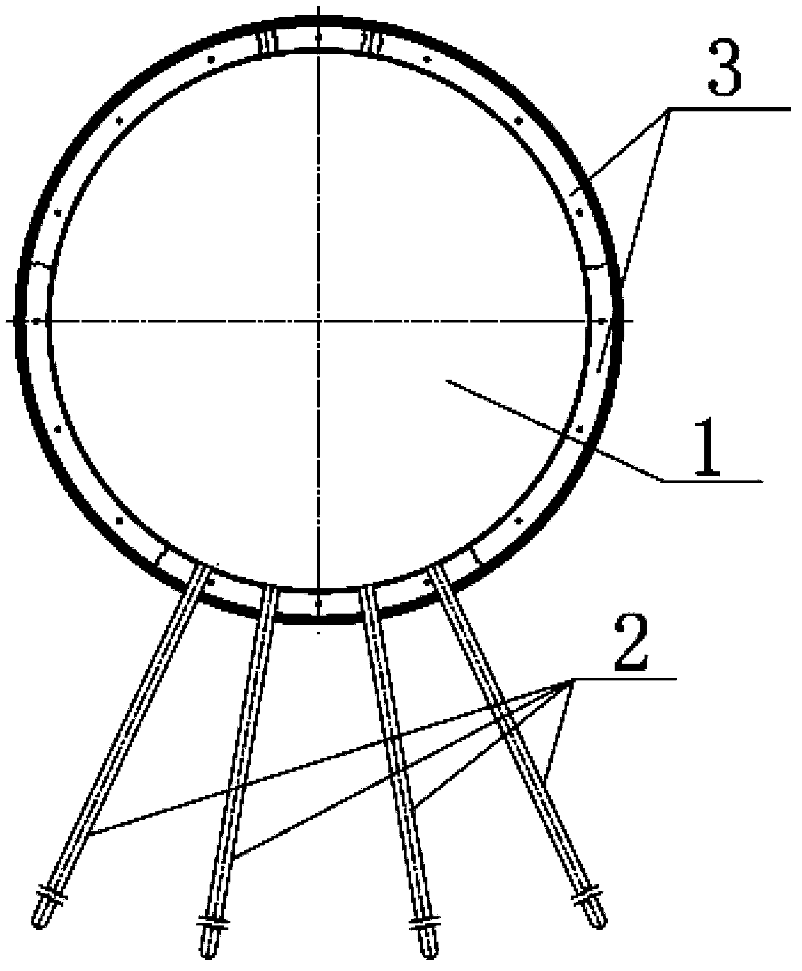
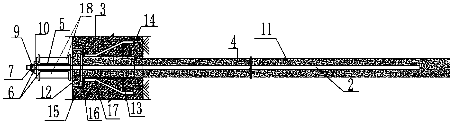
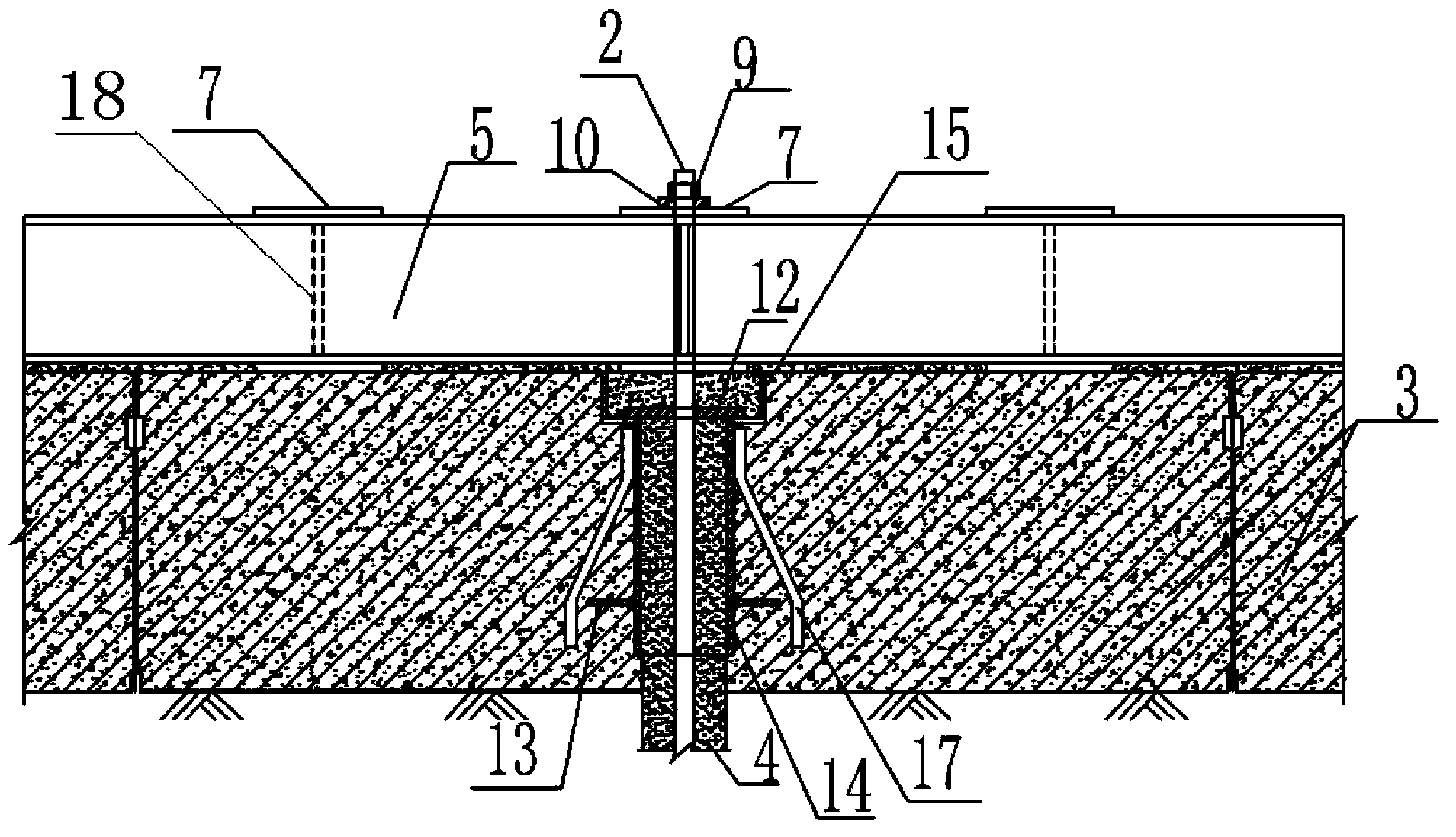
[0020] as attached figure 1 Shown is the structural representation of the anti-floating structure of the shallow buried shield method tunnel of the present invention, as attached figure 2 The schematic diagram of the specific implementation of the anti-floating structure anchor rod of a kind of shallow buried shield method tunnel is shown, including the anchor rod fixing hole opened radially downward along the inner surface of the segment 3 of the tunnel 1, and the anchor rod fixing hole set in the anchor rod fixing hole Anchor rod 2 inside. Exemplarily, the anchor rod 2 may be a mortar anchor rod.

[0021] In other specific embodiments, the anchor rod 2 can also be other anti-floating piles such as micro piles, and the cement mortar filled in the fixing holes of the anti-floating piles can be used to bond with the surrounding rock, and the anchor rod fixing holes can also be vertically downward. Or open downward at any angle.

[0022] In the actual operation of the projec...


PUM


Abstract

The invention discloses an anti-floating structure of a shallow-buried shield tunnel. The structure comprises anti-floating pile fixing holes, anti-floating piles, a plurality of steel structural beams and waterproof structures, wherein anti-floating pile fixing holes are arranged downwards along inner surfaces of tunnel segments, at least part of anti-floating piles are arranged in anti-floating pile fixing holes, waterproof structures are embedded inside tunnel segments, a plurality of anti-floating piles which are arranged coaxially along inner surfaces of tunnel segments are fixedly arranged on the same steel structural beam, waterproof structures comprise steel pipe bodies and steel water sealing rings, sealing end plates are arranged inside steel pipe bodies, steel water sealing rings are arranged on outer sides of steel pipe bodies, anti-floating pile holes are arranged on sealing end plates, waterproof structures are arranged above anti-floating pile fixing holes, anti-floating piles penetrates through anti-floating pile holes and anti-floating pile fixing holes, steel pipe bodies comprise first steel pipes and second steel pipes, and first steel pipes and second steel pipes are arranged coaxially. The structure meets the anti-floating requirements of the shallow-buried shield tunnel and can be used on the condition that uplift pile construction conditions or foundation pit bottom plates do not exist around the constructed shallow-buried tunnel.

Description

technical field [0001] The invention relates to an anti-floating structure of an underground tunnel, in particular to an anti-floating structure of a shallow-buried shield tunnel. Background technique [0002] The buried depth of the traditional shield method tunnel is relatively deep, and the round tunnel can meet the anti-floating requirements through the deep covering soil pressure. However, when the tunnel is limited by the length of the connection, it is necessary to use the shallow buried shield method for construction, or to excavate at the top of the existing tunnel. When unloading, the round tunnel often cannot meet the anti-floating requirements by relying on the overlying soil and the self-weight of the segments. [0003] Chinese invention patent 200620049257.7 proposes a door-type anti-floating structure in order to solve the problem that the excavation of the foundation pit above the subway can not meet the anti-floating requirements. The structure is composed o...

Claims


Application Information

Patent Timeline
IPC IPC(8): E02D31/12E21D9/14
Inventor 姜弘王印昌潘国庆王新张银屏滕丽李刚林家祥卓发成
Owner SHANGHAI URBAN CONSTR DESIGN RES INST GRP CO LTD
Why Eureka
Try Eureka