Plug pin positioning and locking device

A technology of positioning locking and positioning keys, applied in the direction of bolts, etc., can solve the problems of inconvenient operation, time-consuming and laborious, etc., and achieve the effects of compact structure, time-saving and labor-saving use, and convenient operation

Active Publication Date: 2012-11-14
江苏捷诚车载电子信息工程有限公司
View PDF5 Cites 19 Cited by
  • Summary
  • Abstract
  • Description
  • Claims
  • Application Information

AI Technical Summary

Problems solved by technology

The existing vehicle-mounted equipment positioning and locking device adopts a straight tube structure. After pulling the handle, it rotates 90° to achieve locking or unlocking. The disadvantage of this device is that it is inconvenient to operate, and the user is required to have a certain amount of arm strength to pull the handle horizontally to the device. To lock or unlock, you need to adjust the angle of the handle to make the device firmly locked, which is time-consuming and laborious to use

Method used


Image

  • Plug pin positioning and locking device
  • Plug pin positioning and locking device
  • Plug pin positioning and locking device

Examples


Embodiment Construction

[0015] The present invention will be further described below in conjunction with drawings and embodiments.

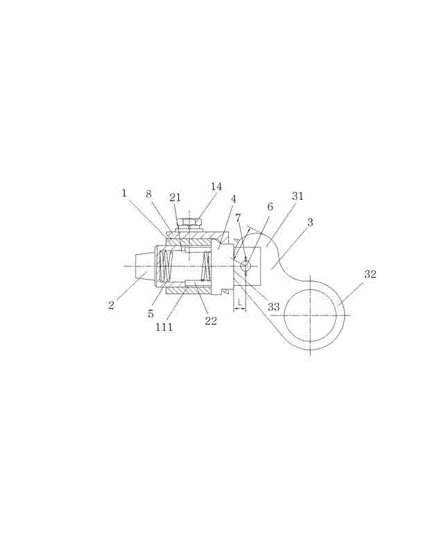
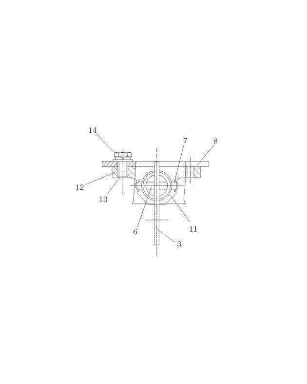
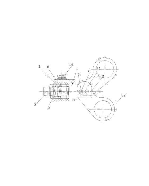
[0016] Such as figure 1 and figure 2 As shown, the present invention includes a base 1, a latch 2, a handle 3, a positioning key 4 and a spring 5. The base 1 is T-shaped and includes a base body 11 and an upper plate 12 extending from the upper side of the base body 11 to both sides. , the two ends of the upper plate 12 are provided with threaded holes 13, and the base 1 is fixed on a mobile platform such as a van or a vehicle-mounted shelter by fastening screws 14. The base 1 of this embodiment is fastened by two Screw 14 is fixed on the angle steel 8 of van or vehicle-mounted shelter. The base body 11 is provided with a base hole 111 that runs through the front and back. The latch 2 is slidingly fitted with the base hole 111. The front end of the latch 2 is a truncated cone, which can be retracted into and out of the locked device. The truncated cone structure is c...


PUM


Abstract

The invention discloses a plug pin positioning and locking device which comprises a base, a plug pin, a handle, a spring and a positioning key; a base body is provided with a base hole which runs through front and back; the plug pin is in sliding fit with the base hole; the front end of the plug pin can pass in and out of a locked device elastically; the rear end of the plug pin is provided with an axial counter bore; the center of the rear end of the axial counter bore is provided with a handle groove which runs through up and down; a positioning key is of a sheet shape, and is positioned between the spring and the handle; the front end of the positioning key is embedded on the rear end of the base; the spring is positioned in the axial counter bore, and the rear end of the spring butts against the front end of the positioning key; the front end of the handle is embedded in the handle groove at the rear end of the plug pin, butts against the rear end of the positioning key, and is articulated with the rear end of the plug pin through a horizontal pin. The plug pin positioning and locking device provided by the invention is compact in structure, is simple in process, is convenient and rapid to operate, is low in cost, is small in occupied space, is safe and reliable, is wide in applicability, is time-saving and labor-saving in use, and is rapid in positioning and locking capability.

Description

technical field [0001] The invention relates to a positioning and locking device for a locked object, in particular to a positioning and locking device for fast position limitation by rotating a handle, which belongs to the technical field of hardware accessories. Background technique [0002] The equipment that is quickly disassembled or installed needs to be locked by a limit locking device to ensure the safe use of the equipment in a moving state. The equipment loaded on a mobile platform such as a van or a vehicle shelter needs to be locked reliably when the vehicle is driving, and it needs to be quickly unlocked when the vehicle is parked, so that the vehicle equipment can be disassembled and transferred outside the vehicle for use. The existing positioning and locking device for vehicle-mounted equipment adopts a straight tube structure. After pulling the handle, it rotates 90° to achieve locking or unlocking. The disadvantage of this device is that it is inconvenient...

Claims


Application Information

Patent Timeline
Patent Type & Authority Applications(China)
IPC IPC(8): F16B19/02
Inventor 张正玲
Owner 江苏捷诚车载电子信息工程有限公司
Why Eureka
Try Eureka