
Self-powered electric power circuit fault detector

A fault indicator and power line technology, applied in the direction of instruments, measuring electricity, measuring electrical variables, etc., can solve problems such as insufficient power supply, and achieve the effect of extending the service life and expanding functions

Inactive Publication Date: 2012-11-14
BEIJING FEIJU ELECTRIC
View PDF6 Cites 0 Cited by
  • Summary
  • Abstract
  • Description
  • Claims
  • Application Information

AI Technical Summary

Problems solved by technology

[0008] The purpose of the present invention is to provide a self-powered line fault indicator to solve the problem of insufficient power supply of the existing power overhead line fault indicator

Method used


Image

  • Self-powered electric power circuit fault detector
  • Self-powered electric power circuit fault detector

Examples


Embodiment Construction

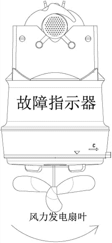
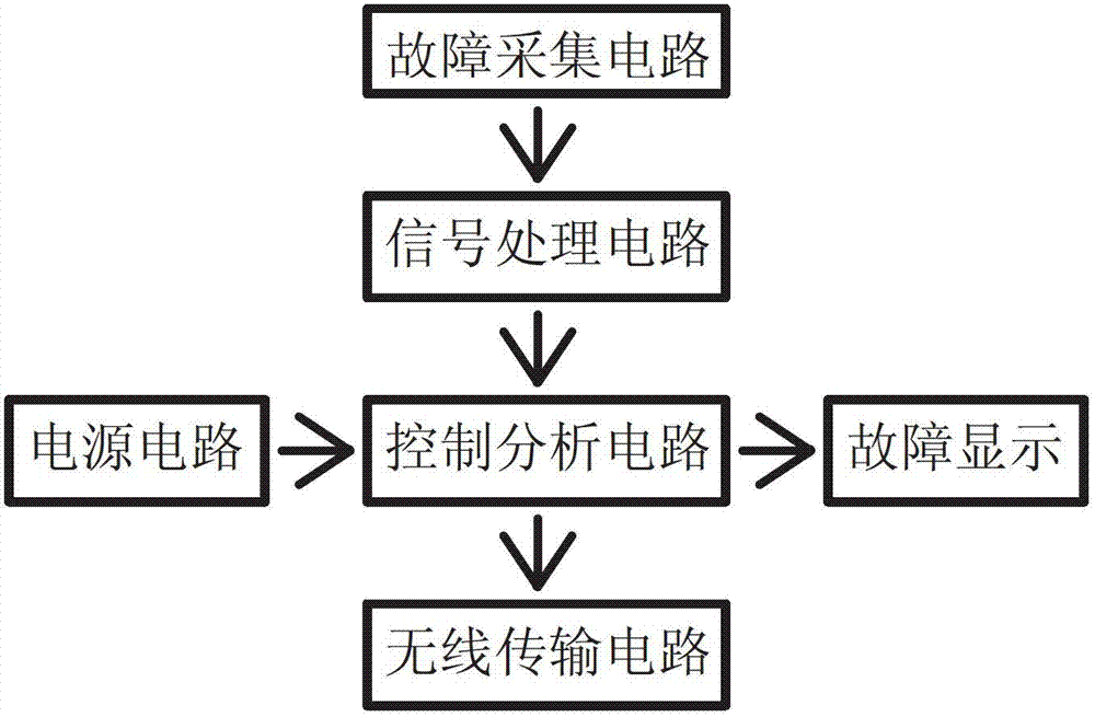
[0027] The invention is a self-powered power line fault indicator, which includes a power line fault indicator and a miniature wind power generation system. The micro wind power generation system and the power line fault indicator are integrated to supply power to the power line fault indicator.

[0028] further:

[0029] The micro-wind power generation system is composed of vertical-axis fan blades, a transmission, a micro-generator, an electric energy storage unit, and a rectification protection circuit.

[0030] The vertical shaft fan blade is installed in the center directly below the fault indicator; the transmission is installed inside the fault indicator housing; the micro-generator is installed inside the fault indicator housing and connected to the fan blade through the transmission; The input of the rectification protection circuit is connected to the output of the micro generator, and the output of the rectification protection circuit is connected to the electric en...


PUM


Abstract

The invention discloses a self-powered electric power circuit fault detector which is formed by combining an electric power overhead circuit fault detector and a miniature wind power generation system. The self-powered electric power circuit fault detector comprises the power circuit fault detector and the miniature wind power generation system which are integrally combined to supply power for the electric power circuit fault detector. The self-powered electric power circuit fault detector has the advantages of (1) sufficiently using natural wind energy resources on a high altitude overhead line; (2) providing continuous, sufficient and stable electric power energy for the fault detector; (3) greatly prolonging service life of the fault detector; (4) being energy-saving, environment-friendly and high in efficiency and meeting national policies; and (5) being capable of greatly expanding functions of the existing fault detector due to sufficient power supply.

Description

technical field [0001] The invention relates to a novel self-powered line fault indicator. Background technique [0002] The power line fault indicator is a fault information indicating device used to detect and indicate whether the fault circuit of the user's power line flows through it. Its working principle is that when the power line fails, due to the sudden change of electrical parameters in the line, changes in the magnetic field and electric field around the power line are generated. The control circuit inside the power line fault indicator monitors these variables and automatically judges whether the fault circuit flows through Here, an alarm signal is further output to drive the display part to work, and an alarm flashes a red indicator light, so as to achieve the purpose of indicating the failure of the faulty line. [0003] Existing power line fault indicators suffer from some of the following disadvantages: [0004] 1. Some products are powered by solid-state b...

Claims


Application Information

Patent Timeline
IPC IPC(8): G01R31/00
Inventor 鲍伟鄢素云董永清
Owner BEIJING FEIJU ELECTRIC
Learn More