Eureka AIR delivers breakthrough ideas for toughest innovation challenges, trusted by R&D personnel around the world.

Coal rock identification system and device

A coal-rock identification and subsystem technology, applied in the field of coal-rock identification systems and devices, can solve problems such as the coal mining face is advanced and the mining head cannot be adjusted in time, so as to prolong the service life and prevent damage

Pending Publication Date: 2020-07-14
CHINA COAL TECH ENG GRP CHONGQING RES INST
View PDF0 Cites 1 Cited by
  • Summary
  • Abstract
  • Description
  • Claims
  • Application Information

AI Technical Summary

Problems solved by technology

[0003] Aiming at the problem that the mining head cannot be adjusted in time in the prior art, the present invention proposes an identification system and device, which collects coal wall images in real time through the image acquisition module, then extracts feature vectors and inputs them to the controller to identify the type of coal rock, thereby Realize advanced coal and rock identification in coal mining face

Method used


Image

  • Coal rock identification system and device
  • Coal rock identification system and device
  • Coal rock identification system and device

Examples


Embodiment 1

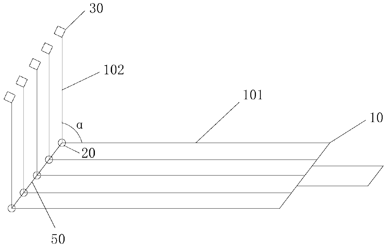
[0052] Such as figure 2 As shown, the support 10 is used to rigidly connect with the coal shearer; the support 10 includes two sides, one side connected to the coal shearer is the first side 101, and one side in contact with the coal wall is the second side 102, The angle between the second side surface 102 and the first side surface 101 is α, 0°≤α<180°, generally set to 60°≤α<150°.

[0053] In this embodiment, n brackets 10 are parallel to each other (n brackets 10 may not be parallel to each other, that is, the first side 101 can intersect), and are fixed together by connecting rods 50, that is, in each bracket 10 A connecting rod 50 is installed at the intersection of one side 101 and the second side 102 to fix the n brackets 10, and the image acquisition sensor 20 is installed on the connecting rod 50 at the intersection of the first side 101 and the second side 102, and the acquisition corresponds to The coal rock image is transmitted to the controller for coal rock ide...

Embodiment 2

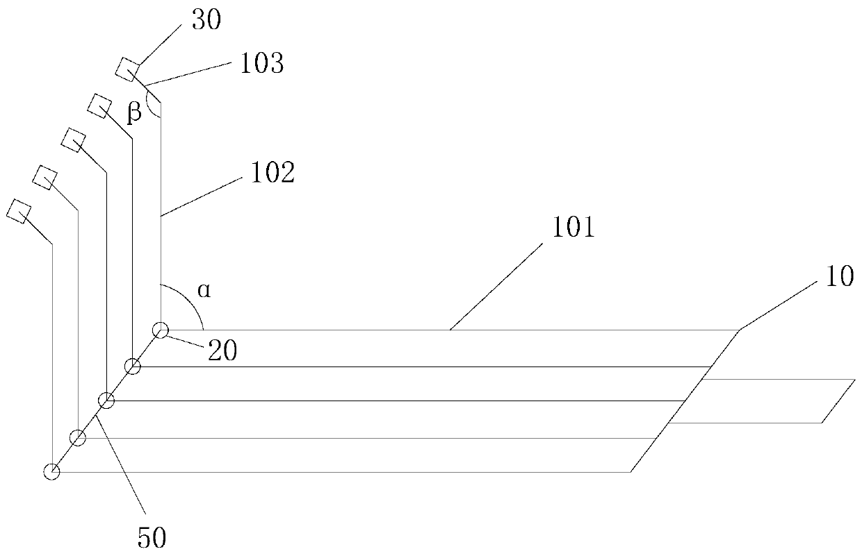
[0057] Such as image 3 As shown, the support 10 is used for rigid connection with the shearer; the support 10 includes three sides, one side connected with the shearer is the first side 101, and one side close to the coal wall (not in contact with the coal wall) is The second side 102, the angle between the second side 102 and the first side 101 is α, 0°≤α<180°; one side in contact with the coal wall is the third side 103, the third side 103 and the second The included angle between the side surfaces 102 is β, α<β<α+90°, and the third side 103 deflects away from the shearer, which facilitates the installation of the static penetrating sensor on the third side 103, The coal and rock in the coal wall can be identified in advance. The advantage of setting the third side 103 is to facilitate the installation of the static penetration sensor 30, and the static penetration sensor 30 can detect and identify the coal and rock in the coal wall in advance when the shearer is moving, s...


PUM


Abstract

The invention discloses a coal rock identification system and device. A first identification subsystem comprises an image acquisition module or a static sounding array module, an image processing module, an image identification module and a signal identification module; the image acquisition module transmits a collected coal rock image in a coal wall and corresponding space coordinates to the image processing module so as to extract feature vectors of the coal rock image; the image identification module identifies coal and the rock according to the extracted feature vectors; and a controller adjusts the height of a coal cutter roller according to the identified rock image and the corresponding space coordinates to avoid rocks in the coal wall. According to the coal rock identification system, the image processing technology is adopted to identify the coal rock of a coal face in advance, and the height of the coal cutter roller is adjusted according to the identifying result, so that the coal bed is excavated as much as possible, hard rock is avoided, the tool face of the coal cutter is prevented from being damaged, the service life of the coal cutter and other coal mining equipmentis prolonged, and a guiding significance is played in intelligent mining of the coal face.

Description

technical field [0001] The invention relates to the technical field of coal mine intelligence, in particular to a coal rock identification system and device. Background technique [0002] Shearer is one of the main equipments in the comprehensive mechanized coal mining face. At present, all kinds of shearers work according to the set fixed mining route. When the mining head of the coal mining machine cuts the rock, on the one hand, the wear of the mining head of the coal mining machine will increase, the power consumption will increase, and even the gas will be detonated due to the high temperature generated by the excessive friction of the mining head; The gangue content in the coal increases. Solving the above problems at present is to be solved by the on-site operator shutting down in time to adjust the position of the mining head, and the labor intensity and danger of the workers are great. Contents of the invention [0003] Aiming at the problem that the mining head...

Claims


Application Information

Patent Timeline
IPC IPC(8): E21C39/00E21C35/24G06T7/70G06K9/62
CPCE21C39/00E21C35/24G06T7/70G06F18/22
Inventor 李云波单礼岩胡运兵张军孙喆阎家光何昭友谢成梁康厚清杨鹏飞赵哲
Owner CHINA COAL TECH ENG GRP CHONGQING RES INST
Why Eureka
Eureka Blog
Learn More