Micro base station antenna

A micro base station and antenna technology, applied in the field of communication, can solve problems such as inconvenience, and achieve the effects of less intermodulation factors, good intermodulation and simple structure

Active Publication Date: 2012-11-14
MOBILE ANTENNA TECH SHENZHEN +2
View PDF5 Cites 8 Cited by
  • Summary
  • Abstract
  • Description
  • Claims
  • Application Information

AI Technical Summary

Problems solved by technology

[0004] In summary, the existing micro base station antenna technology obviously has inconvenience and defects in actual use, so it is necessary to improve it

Method used


Image

  • Micro base station antenna
  • Micro base station antenna
  • Micro base station antenna

Examples


Embodiment Construction

[0023] In order to make the object, technical solution and advantages of the present invention clearer, the present invention will be further described in detail below in conjunction with the accompanying drawings and embodiments. It should be understood that the specific embodiments described here are only used to explain the present invention, not to limit the present invention.

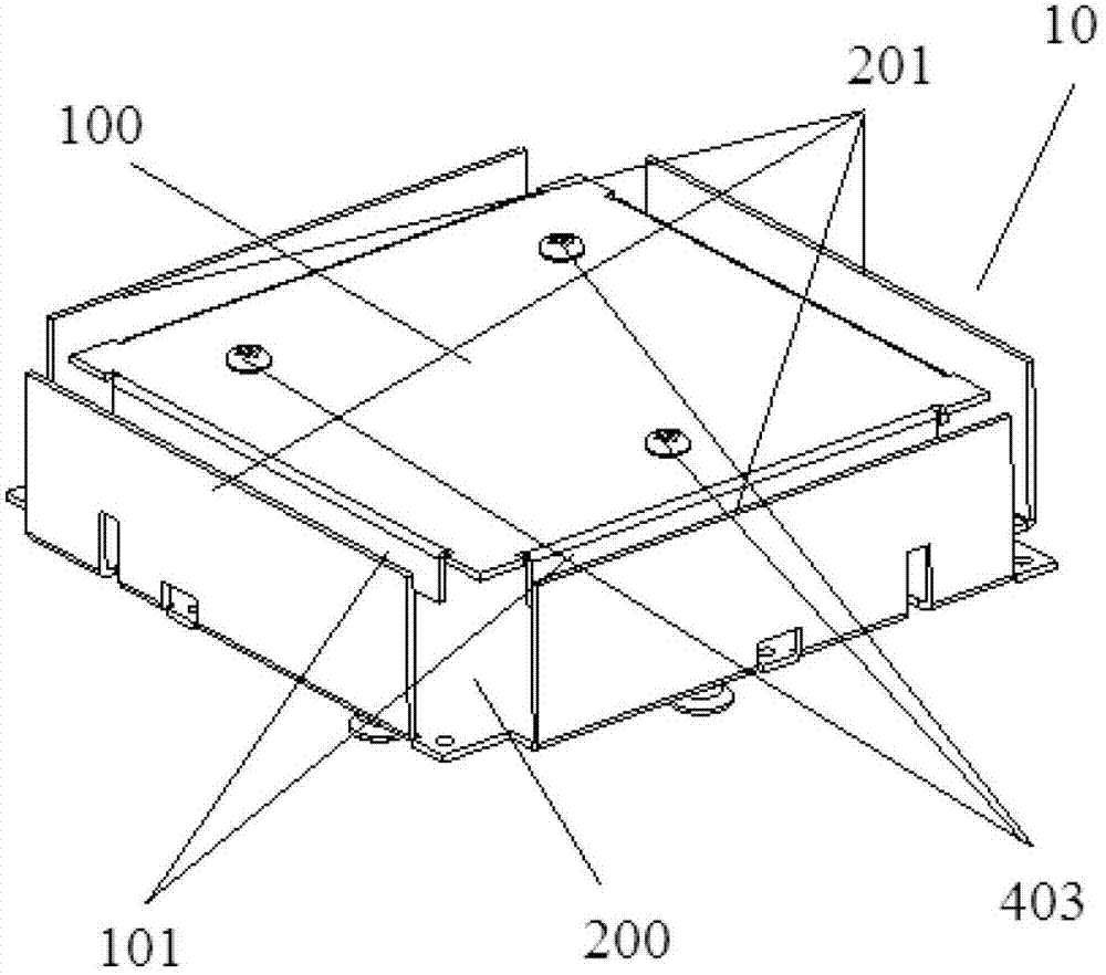
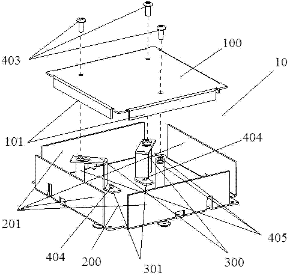
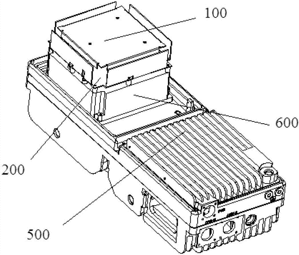
[0024] see figure 1 with figure 2 , in one embodiment of the present invention, a micro base station antenna 10 is provided, including:

[0025] The radiator 100 is covered on the upper end of the reflector 200;

[0026] The reflector 200 is in the shape of a square, and a plurality of feeding sheets 300 are arranged in the reflector 200;

[0027] A plurality of feeding sheets 300 are disposed in the reflector 200 .

[0028] In this embodiment, the provided micro base station antenna 10 has an integrated miniaturized dual-polarized micro base station radiation unit with extremely simple struct...


PUM


Abstract

The invention is applicable to the technical field of communication and provides a micro base station antenna. The micro base station antenna comprises a radiating body, a reflector and a plurality of feed sheets, wherein the radiating body is covered at the upper end of the reflector, the reflector is in a cuboid shape, and the plurality of feed sheets are arranged in the reflector. Accordingly, the micro base station antenna with a small size still has good radiating and circuit characteristics.

Description

technical field [0001] The present invention relates to the technical field of communications, in particular to a micro base station antenna. Background technique [0002] With the development of mobile networks and services, operator competition is becoming increasingly fierce, and user requirements are becoming more sophisticated and professional. The scope of mobile network penetration is gradually expanding. In order to solve the coverage problem, traditional solutions include adding macro base stations, micro base stations combined with traditional indoor distribution systems, or repeaters combined with traditional indoor distribution systems. [0003] For the micro base station coverage scheme, the micro base station must be small, beautiful, easy to beautify and flexible in form in its special application environment. The integrated micro base station solution that integrates miniaturized antennas, miniaturized radio frequency processing components, and miniaturized ...

Claims


Application Information

Patent Timeline
Patent Type & Authority Applications(China)
IPC IPC(8): H01Q1/36H01Q15/18H01Q19/10H01Q1/50
Inventor 骆胜军陆洋袁帅潘波
Owner MOBILE ANTENNA TECH SHENZHEN
Why Eureka
Try Eureka