Cable connection device and explosion-proof electric control box

A technology for cable connection and electric control box, which is applied in the direction of electrical components, sealed enclosures, etc., can solve the problems of inconvenient operation, damage to the connecting section, and reduction of the efficiency of the test.

Inactive Publication Date: 2012-11-14
SANY HEAVY EQUIP
View PDF5 Cites 3 Cited by
  • Summary
  • Abstract
  • Description
  • Claims
  • Application Information

AI Technical Summary

Problems solved by technology

[0005] 1) Since the Unicom joint is welded on the electric control box, it is easy to damage and deform the electric control box during welding;
[0006] 2) The Unicom joint is easily damaged under high-pressure water flow when pressing;
[0007] 3) When installing elbows and other devices and pulling cables, since the connecting joint has been welded to the guard plate, it is equivalent to operating the entire electric control box, which is not convenient enough;
[0008] 4) Due to the need to block the through hole on the guard plate during pressing, but the through hole is welded with a joint joint, forming a raised structure, which is difficult to block. In practice, it is often used to block when pressing The tooling of the through hole is punched open, which reduces the efficiency of the test

Method used


Image

  • Cable connection device and explosion-proof electric control box
  • Cable connection device and explosion-proof electric control box
  • Cable connection device and explosion-proof electric control box

Examples


Embodiment Construction

[0032] In order to understand the above-mentioned purpose, features and advantages of the present invention more clearly, the present invention will be further described in detail below in conjunction with the accompanying drawings and specific embodiments.

[0033] In the following description, many specific details are set forth in order to fully understand the present invention. However, the present invention can also be implemented in other ways different from those described here. Therefore, the protection scope of the present invention is not limited by the specific details disclosed below. EXAMPLE LIMITATIONS.

[0034] The present invention will be further described below in conjunction with the accompanying drawings and embodiments. It should be noted that, in the case of no conflict, the embodiments of the present application and the features in the embodiments can be combined with each other.

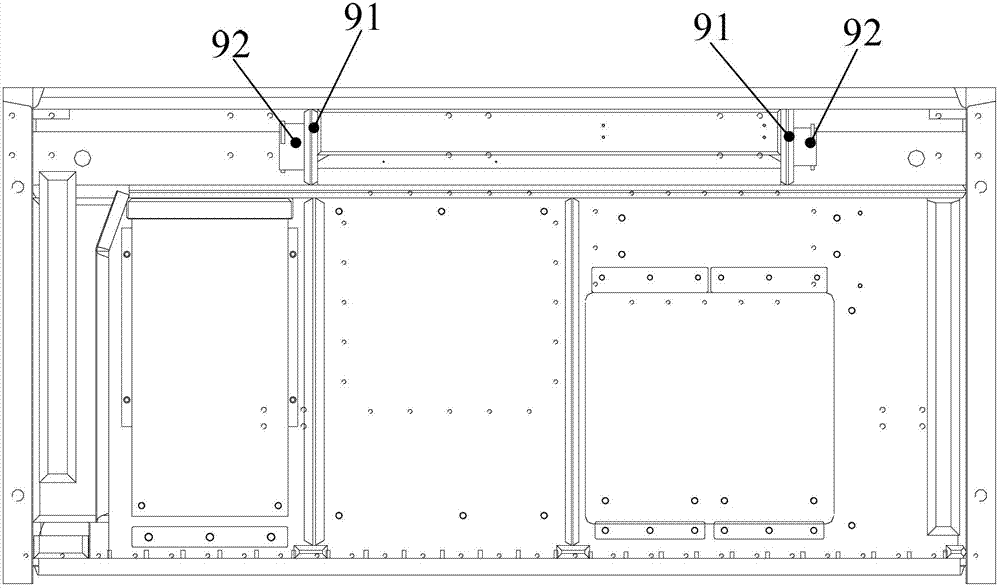
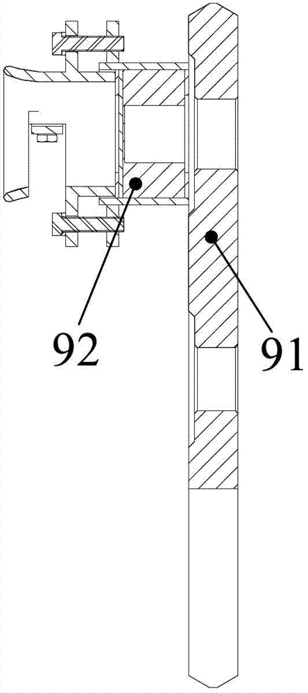
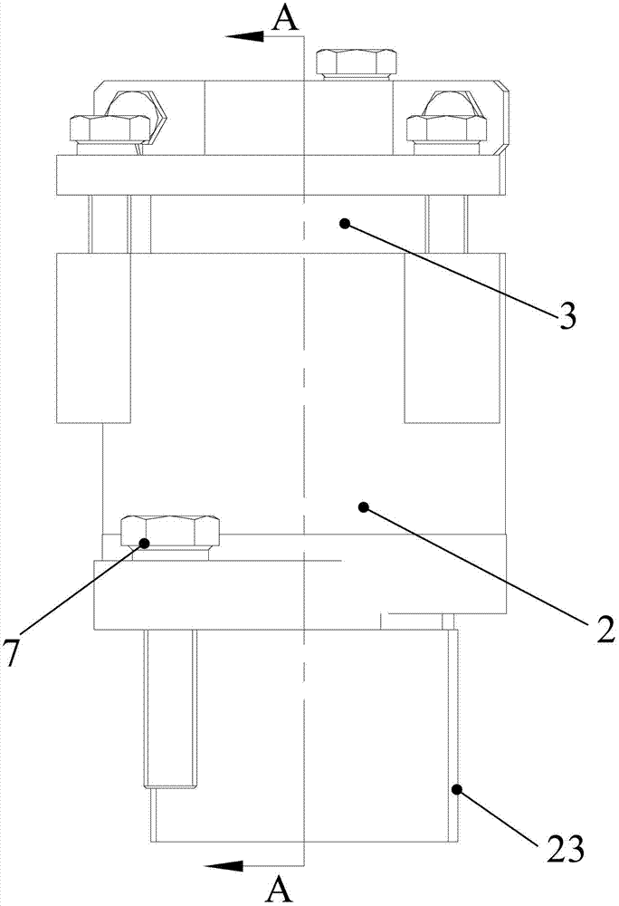
[0035] As shown in the figure, the cable connection device 10 provided b...


PUM


Abstract

The invention provides a cable connection device which is used for an explosion-proof electric control box. The cable connection device comprises a connection part, a sealing ring and a fixation part, wherein a first through hole is formed on the connection part; a second through hole is formed on the fixation part; and in the explosion-proof electric control box, a cable penetrates through the first through hole, the second through hole and a protection plate in the explosion-proof electric control box respectively; the first through hole is a step hole; the sealing ring is arranged on the part with a large inner diameter in the first through hole; the fixation part is detachably connected to one end of the connection part and used for tightly pressing the sealing ring on steps in the step hole, and the other end of the connection part stretches in the through hole of the protection plate and is detachably connected with the protection plate. The cable connection device provided by the invention cannot damage the electric control box during installation because welding is not needed, installation for devices such as an elbow and dragging for the cable are more convenient, and the cable connection device has no need to be installed on the electric control box during a bulge test, so that the damage of the bulge test on the cable connection device is avoided. The invention further provides the explosion-proof electric control box.

Description

technical field [0001] The invention relates to the field of explosion-proof devices, in particular to a cable connection device and an explosion-proof electric control box. Background technique [0002] Pressurization refers to the use of high-pressure water flow to flush the explosion-proof equipment to test the tightness of the solder joints on the explosion-proof equipment. [0003] The structure of the explosion-proof electric control box is as follows: figure 1 As shown, the picture shows a larger chamber of the electric control box, and there is a smaller chamber behind the electric control box. In actual use, the cable will pass through the protective plate from the smaller chamber at the back 91 into the larger chamber that can be seen in the figure. Due to explosion-proof requirements, it is necessary to seal the portion of the through hole on the guard plate 91 passing through the cable after the cable passes through the guard plate 91 . In existing related tec...

Claims


Application Information

Patent Timeline
Patent Type & Authority Applications(China)
IPC IPC(8): H02G3/22H05K5/06
Inventor 刘丹张祚明刘磊
Owner SANY HEAVY EQUIP
Why Eureka
Try Eureka