Radio frequency device

A radio frequency device and accommodating cavity technology, applied in the direction of electrical components, transmission systems, connecting contact materials, etc., can solve the problems of high antenna connection costs, save resources and energy, facilitate large-scale production and reduce processing and manufacturing cost effect

Active Publication Date: 2012-11-14
KUANG CHI INST OF ADVANCED TECH
View PDF7 Cites 8 Cited by
  • Summary
  • Abstract
  • Description
  • Claims
  • Application Information

AI Technical Summary

Problems solved by technology

[0004] In order to solve the problem of high antenna connection cost in the existing radio frequency device, the present invention provides a radio frequency device, which simplifies the process and reduces the cost by optimizing the connection mode between the antenna and the radio frequency device, in order to achieve the above purpose , the present invention adopts the following technical solutions:

Method used


Image

  • Radio frequency device
  • Radio frequency device
  • Radio frequency device

Examples


Embodiment Construction

[0022] Reference will now be made in detail to the embodiments depicted in the accompanying drawings. In the following detailed description, numerous specific details are set forth in order to provide a thorough understanding of the present invention. However, it will be understood by those skilled in the art that the present invention may be practiced without these specific details. In other instances, well-known methods are not described in detail. procedures, components and circuits so as not to unnecessarily obscure the embodiments.

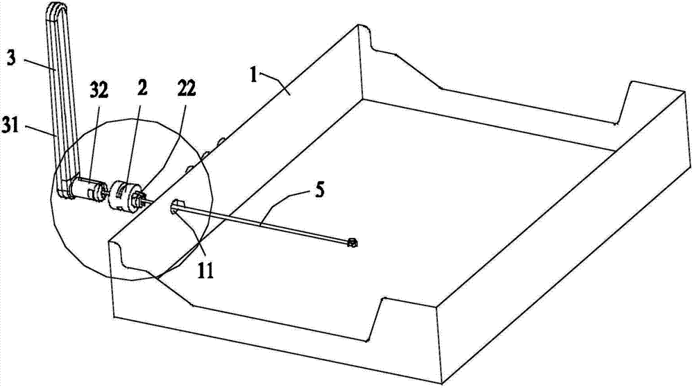
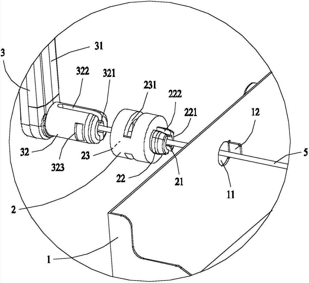
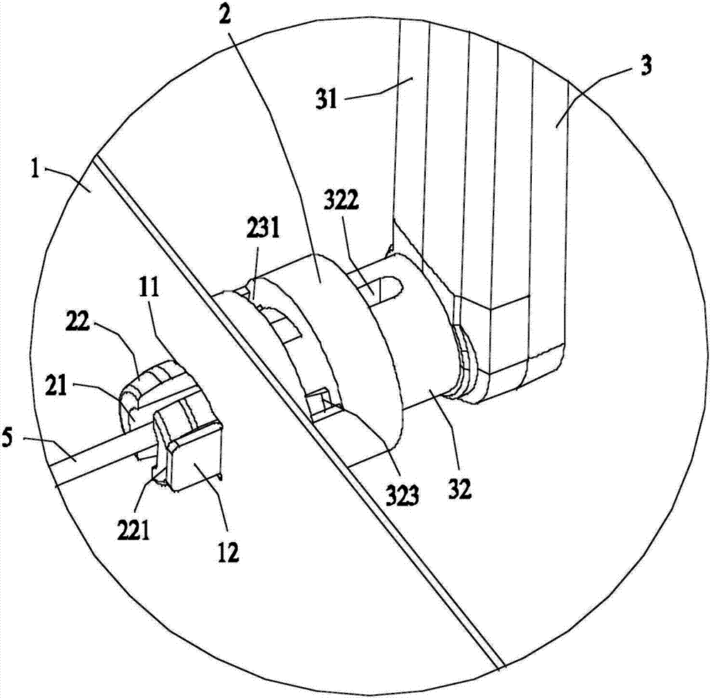
[0023] see figure 1 , figure 2 Shown is a schematic structural diagram of an embodiment of the radio frequency device of the present invention, the radio frequency device includes a housing 1, a circuit board (not shown in the figure), a connector 2, an antenna 3 and a signal transmission line 5, and on one side of the housing 1 A circular socket 11 and a blocking piece 12 are provided. The blocking piece 12 is approximately cuboid, and ...


PUM


Abstract

The invention provides a radio frequency device, which comprises a shell, a circuit board, an antenna, a signal transmission line and a connecting piece, wherein the circuit board is arranged in the shell; the antenna is arranged outside the shell; the signal transmission line is used for connecting the circuit board with the antenna; one side surface of the shell is provided with a jack; the antenna comprises an antenna body and a plugging part with a line hole, wherein the plugging part is connected with the antenna body; the cylindrical surface of the plugging part is provided with a lug; the connecting piece is similar to a ladder cylinder shape; the connecting piece comprises a through hole, a plug and a containing cavity, wherein the plug comprises a restriction part which can prevent the connecting piece from rotating around the axis on the ladder trend; the wall of the containing cavity is provided with a ring slot; the plug can be cooperatively plugged into the jack; the plugging part is arranged in the containing cavity in a transition fit mode; the lug is clamped into the ring slot; and the antenna body is connected to the circuit board via the signal transmission line. According to the radio frequency device disclosed by the invention, the connection mode of the antenna and the radio frequency device is optimized, and the cost is lowered, thereby being convenient for large-scale production and manufacture.

Description

technical field [0001] The invention belongs to the field of communication equipment, and in particular relates to a radio frequency device. Background technique [0002] In recent years, with the development of wireless communication, radio frequency devices have been widely used, and radio frequency devices transmit and receive wireless signals through antennas. Wireless signals use radio frequency technology. In order to obtain better communication effects, sometimes it is necessary to adjust the direction of the antenna to obtain the best radiation angle. [0003] In order to achieve a better communication effect, the current radio frequency equipment uses an external antenna, and often uses a coaxial connector to connect the antenna and the radio frequency equipment to transmit radio frequency signals. The basic structure of the coaxial connector includes: a central conductor, The dielectric material (insulator) outside the inner conductor and the outermost outer conta...

Claims


Application Information

Patent Timeline
Patent Type & Authority Applications(China)
IPC IPC(8): H04B1/38H01R4/58
Inventor 刘若鹏吕晶
Owner KUANG CHI INST OF ADVANCED TECH
Why Eureka
Try Eureka