
Cover view gripper

A gripper and container technology, which is applied in the field of cover seat inspection and labeling device, can solve the problems that the sealing element is not closed correctly, the sealing element is not seated correctly, etc.

Inactive Publication Date: 2012-11-14
KHS GMBH
View PDF8 Cites 5 Cited by
  • Summary
  • Abstract
  • Description
  • Claims
  • Application Information

AI Technical Summary

Problems solved by technology

That is, the closure element may be seated incorrectly, i.e. the closure element does not close the container properly

Method used


Image

  • Cover view gripper
  • Cover view gripper
  • Cover view gripper

Examples


Embodiment Construction

[0031] In the various figures, the same components are always identified by the same reference numerals, so that they are only described once.

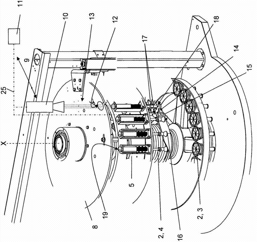
[0032] figure 1 A container handling device 1 is shown, in the exemplary embodiment as a labeling machine or a labeling carousel. The container handling device 1 has a plurality of centering devices 2 each having a standing surface 3 and a container gripper 4 .

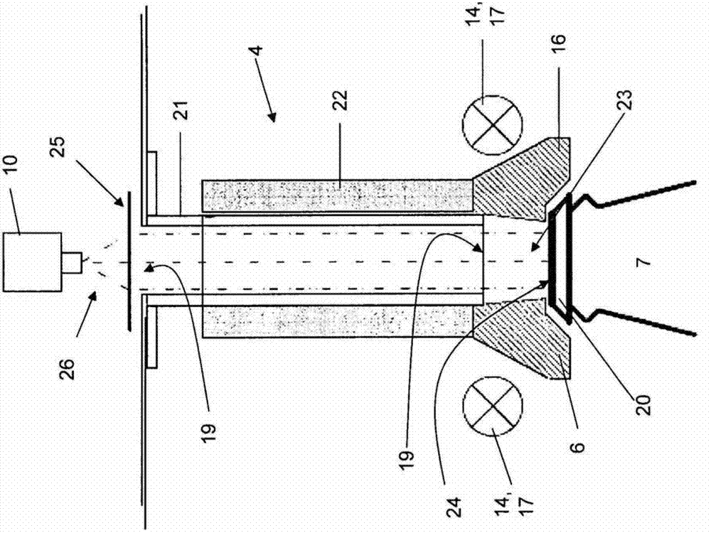
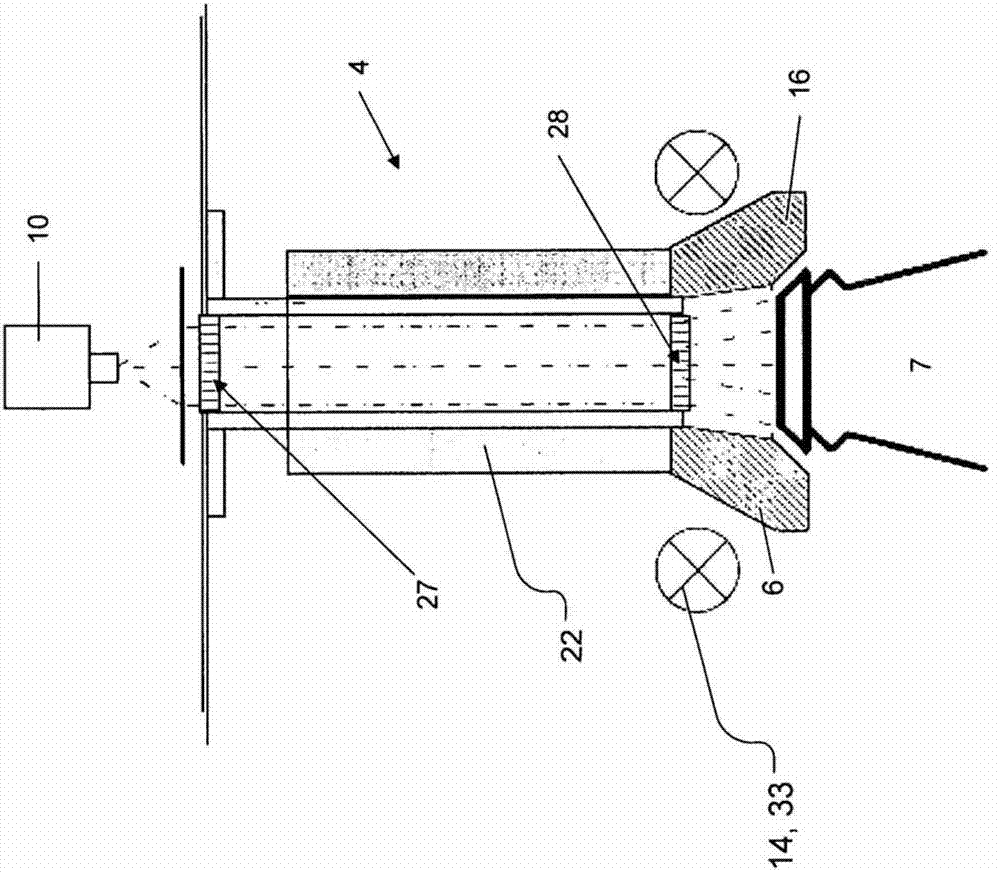
[0033] The standing surface 3 is provided in a known manner as a turntable 3 , wherein the container gripper 4 is mounted on a drive 5 so that the container gripper can be raised and / or lowered. The centering device 2 makes the container 7 ( Figures 2 to 4 ) eg the bottle is rotated about the central axis X of the container handling device 1 and the container is fed eg to a labeling machine. The container 7 stands with its bottom foot on the corresponding turntable 3 and the head of the container is held by means of the container gripper 4 . Figures 2 to 4 Only the neck...


PUM


Abstract

The invention relates to container handling device (1), in particular a labeling device for bottles, containers, et cetera, which comprises at least one centering device (2), which has a standing surface (3) and a bottle gripper (4), wherein at least one detection and control system (9) having at least one optical system (10) is provided. The bottle gripper (4) has inspection openings (19) both on the head side and on the foot side, wherein at least one light source (14, 17; 14, 33) is provided, and the bottle gripper (4) is at least partially light-conducting or comprises or contains light-conducting elements (6; 30) so that a surface, in particular a cover side (24), can be inspected can be inspected through the optical system and through the bottle gripper (4) and by means of the light-conducting design or light-conducting elements (6; 30) an illuminated inner area (23) can be inspected.

Description

technical field [0001] The invention relates to a container handling device, in particular a labeling device for bottles, containers etc., comprising at least one centering device with a standing surface and a container gripper, wherein at least one detection and a control system, the detection and control system includes at least one optical system. However, the invention also relates to a method for inspection, in particular for lid seat inspection. Background technique [0002] Patent publication DE 3308489 A1 discloses a centering device for erecting vessels, especially in labeling machines, which centering device has a vertical plate, wherein the vertical plate can be lifted from an upper plate held by a stop. The cut-off position moves downward against the force of the spring. The vertical plates are surrounded by a centering ring with a funnel-shaped centering surface adapted to the cross-section of the vessel. The centering cup can be raised and lowered by means o...

Claims


Application Information

Patent Timeline
IPC IPC(8): B65C9/06B67B3/26G01N21/90
CPCB65C9/067G01N21/9054B67B3/262G01N21/909
Inventor J·赫尔曼M·M·赫尔曼
Owner KHS GMBH
Learn More