Phosphor composite member, LED device and method for manufacturing phosphor composite member

A technology of composite components and manufacturing methods, which is applied in the direction of chemical instruments and methods, semiconductor devices, electroluminescent light sources, etc., can solve problems such as shortened life, low white light, and reduced luminous intensity, and achieve simplified manufacturing processes and improved luminous intensity. Excellent, the effect of suppressing the decline over time

Inactive Publication Date: 2012-11-14
NIPPON ELECTRIC GLASS CO LTD
View PDF10 Cites 17 Cited by
  • Summary
  • Abstract
  • Description
  • Claims
  • Application Information

AI Technical Summary

Problems solved by technology

As a result, a reduction in luminous intensity or a color shift occurs, and there is a problem that the life is shortened
[0006] In addition, the obtained white light is a composite light of blue and yellow, so there is a problem that white light with a high color temperature (sunlight color) can be obtained, but white light with a low color temperature (light bulb color, electric spherical color) cannot be obtained.
In addition, since it is synthetic light of two colors, its color rendering is low, making it unsuitable for lighting applications.

Method used


Image

  • Phosphor composite member, LED device and method for manufacturing phosphor composite member
  • Phosphor composite member, LED device and method for manufacturing phosphor composite member
  • Phosphor composite member, LED device and method for manufacturing phosphor composite member

Examples


no. 1 approach )

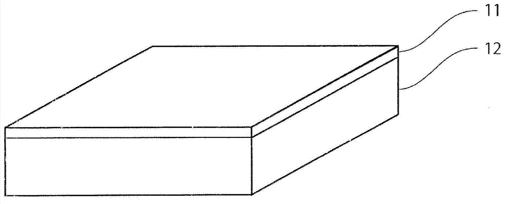
[0066] figure 1 A schematic diagram showing the phosphor composite member of the present embodiment. like figure 1 As shown, the phosphor composite member of this embodiment is characterized in that the surface of the ceramic substrate 12 is formed on the surface of the ceramic substrate 12 2 o 5 The ceramic substrate 12 and the sintered inorganic powder layer 11 emit fluorescence with different wavelengths when irradiated with excitation light.

[0067] Specifically, in the phosphor composite member of this embodiment, it is preferable that the ceramic substrate 12 absorbs light with a wavelength of 400 to 500 nm (preferably blue light) and emits light with a wavelength of 450 to 780 nm (preferably yellow light) when irradiated with excitation light. of fluorescence. In addition, the sintered inorganic powder body layer 11 preferably absorbs light with a wavelength of 400 to 500 nm (preferably blue light) and emits fluorescence with a wavelength of 500 to 780 nm (preferab...

Embodiment )

[0128] Hereinafter, the phosphor composite member of the present invention will be described in detail based on examples, but the present invention is not limited to these examples.

Embodiment 1)

[0130] (1) Preparation of ceramic substrate

[0131] First, using a high-purity raw material with a particle size of 2 μm or less, weigh Y in mole % 2 o 3 37.4625%, Al 2 o 3 62.5%, Ce 2 o 3 0.0375%, making it comply with YAG (Y 3 Al 5 o 12 ) stoichiometric composition, to which 0.6% by mass of tetraethoxysilane was added as a sintering aid. Then, the prepared raw materials were stirred and mixed in ethanol for 17 hours using a ball mill, and then dried under reduced pressure to obtain powder. Next, the obtained powder was press-molded at a pressure of 200 MPa to produce a press-molded body with a diameter of φ10 mm and a thickness of 3 mm, which was fired at 1750° C. for 10 hours in a vacuum atmosphere to obtain a fired body. Then, the fired body was ground on both sides to a thickness of 0.1 mm to obtain a ceramic base material.

[0132] Precipitated crystals were identified using an X-ray powder diffractometer on the ceramic base material thus obtained, and sing...


PUM

PropertyMeasurementUnit
surface roughnessaaaaaaaaaa
thicknessaaaaaaaaaa
particle sizeaaaaaaaaaa

Abstract

Disclosed is a phosphor composite member having excellent heat resistance and colour rendering properties etc. and having colour control capabilities for various colours from daylight colours to light-bulb colours. The phosphor composite member is constituted by forming an inorganic powder sintered body layer containing an inorganic phosphor powder and SnO-P2O5 based glass on the surface of a ceramic substrate. When excitation light is irradiated, the ceramic substrate and the inorganic powder sintered body layer emit fluorescence having mutually different wavelengths.

Description

technical field [0001] The present invention relates to a phosphor composite part, an LED device and a method for manufacturing the phosphor composite part, wherein the phosphor composite part is used to emit fluorescence by irradiating excitation light, and obtain white light by synthesizing transmitted excitation light and fluorescence. Background technique [0002] At present, the following technology has been proposed: by developing blue light-emitting diodes (LED: Light Emitting Diode), LEDs of the three primary colors of light RGB (R: red, G: green, B: blue) are available, and these LEDs are used by arranging them. get white light. However, in general, LEDs of three colors have different luminous powers, so it is difficult to obtain white light by adjusting the characteristics of the LEDs of each color. In addition, even if the LEDs of the three primary colors are arranged on the same plane, a uniform white light source cannot be obtained, for example, when the LEDs a...

Claims


Application Information

Patent Timeline
Patent Type & Authority Applications(China)
IPC IPC(8): C09K11/00C03C3/16C03C3/19C03C8/24C04B41/87C09K11/08C09K11/56C09K11/59C09K11/64H01L33/50
CPCC04B2235/81C04B2235/3418C03C8/14C04B2235/441B32B17/06B32B37/24C04B41/009C04B2235/3229C04B41/86C04B2111/807C04B2235/9646H05B33/14C04B41/5022C03C8/08C09K11/02H01L33/502C04B2235/764C04B2235/5436C04B2235/3225C04B35/44B32B18/00B32B33/00C09K11/7774C04B2237/70C04B35/645C04B37/042C04B2235/6567C04B2235/658C04B2237/343C04B2237/58C04B2237/704Y10T428/24355C04B41/4539C04B41/5027C04B41/5053
Inventor 藤田俊辅铃木良太古山忠仁
Owner NIPPON ELECTRIC GLASS CO LTD
Why Eureka
Try Eureka