Supercharge Your Innovation With Domain-Expert AI Agents!

Component mounting device and component mounting method

A technology of an installation device and installation method, which is applied in the directions of electrical components, electrical components, robots, etc., can solve the problems of increasing the frequency of changing operations, etc.

Active Publication Date: 2012-11-14
PANASONIC INTELLECTUAL PROPERTY MANAGEMENT CO LTD
View PDF8 Cites 2 Cited by
  • Summary
  • Abstract
  • Description
  • Claims
  • Application Information

AI Technical Summary

Problems solved by technology

Therefore, in the component mounting system, as the type of the board as the work object is changed, the frequency of device type changing operations increases

Method used


Image

  • Component mounting device and component mounting method
  • Component mounting device and component mounting method
  • Component mounting device and component mounting method

Examples


Embodiment Construction

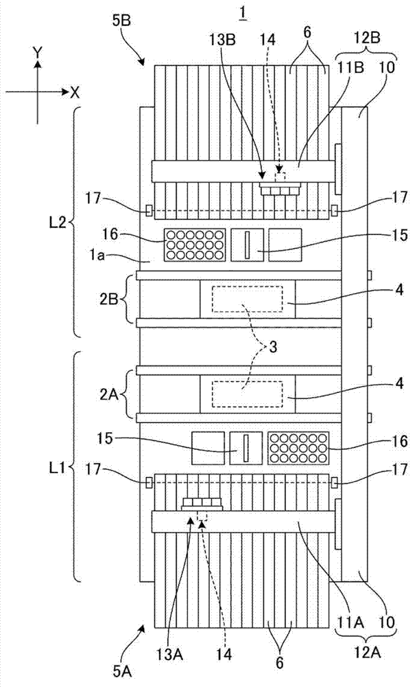
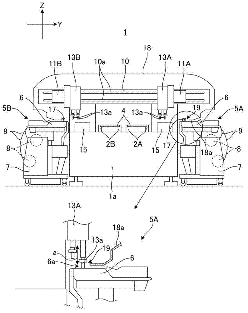
[0035] Next, embodiments of the present invention will be described with reference to the drawings. First, refer to figure 1 and 2 The structure of the component mounting apparatus 1 will be described. exist figure 1In the central part of the base 1a, the first board conveyance mechanism 2A and the second board conveyance mechanism 2B are provided in the X direction (the board conveyance direction), and the first board conveyance mechanism 2A and the second board conveyance mechanism 2B are directed in the X direction. The downstream side in the direction conveys the boards 4 respectively delivered from the upstream device. The first board conveying mechanism 2A and the second board conveying mechanism 2B each have a board supporting portion 3 , and the board supporting portion 3 positions and supports a board 4 conveyed from upstream at a mounting operation position according to a component mounting mechanism described below.

[0036] A first component supply section 5A a...


PUM


Abstract

The purpose of the present invention is to provide a component mounting method, and a component mounting device provided with multiple mounting lanes wherein, when the substrate type is changed, the component mounting device is capable of performing a device type switching operation without stopping operation of the mounting lane in production and without compromising operator safety. A component mounting device provided with a first mounting lane and a second mounting lane is capable of selecting an independent mounting mode and an alternating mounting mode, wherein, when a device type switching operation is performed accompanying a change in the substrate type to be mounted, the mounting head of said mounting lane is moved to and fixed in a position in which the operator can be blocked from inserting a body part through an opening (19) provided on a protective cover (18a), said position being a certain predetermined retracted position [P] such that operator safety is not compromised even upon collision with the mounting head of the opposite-side mounting lane.

Description

technical field [0001] The present invention relates to a component mounting device and a component mounting method for mounting electronic components on a board. Background technique [0002] An electronic component mounting system that manufactures a mounting board by mounting electronic components on a board is formed by combining a plurality of component mounting devices that mount electronic components on a board on which printed Paste for solder bonding. In recent years, in the electronics industry, along with the development of diversification of production modes, a production mode in which various types of products are manufactured in limited quantities is increasingly applied also in the field of component mounting. Therefore, in the component mounting system, as the type of the board as the work object is changed, the frequency of device type changing operations increases. For the purpose of improving productivity in the production field of component mounting, va...

Claims


Application Information

Patent Timeline
IPC IPC(8): H05K13/04
CPCH05K13/0413H05K13/0857Y10T29/53174Y10T29/49998Y10T29/53091Y10T29/5313Y10T29/49169Y10T29/4913Y10T29/49904Y10S901/20H05K13/04
Inventor 北川贵之八木周藏川瀬健之
Owner PANASONIC INTELLECTUAL PROPERTY MANAGEMENT CO LTD
Features
  • R&D
  • Intellectual Property
  • Life Sciences
  • Materials
  • Tech Scout
  • Unparalleled Data Quality
  • Higher Quality Content
  • 60% Fewer Hallucinations
Learn More