Driving device

A driving device and generating device technology, which is applied in the direction of office printing equipment, printing, electrical components, etc., can solve the problems of increased transportation costs, increased packaging costs, and the inability to effectively use the internal space of the transport box, etc., to achieve shortening Necessary time, damage prevention, and the effect of reducing transportation costs

Inactive Publication Date: 2012-11-21
RICOH KK
View PDF6 Cites 0 Cited by
  • Summary
  • Abstract
  • Description
  • Claims
  • Application Information

AI Technical Summary

Problems solved by technology

Therefore, there is a problem that the internal space of the transport box cannot be effectively utilized
[0005] In addition, since the drive unit is packaged and stored in each independent storage space, the time required for the packaging operation is prolonged, and there is also a problem that the packaging cost increases.
[0006] In addition, since the drive units are packaged and stored in separate storage spaces, the number of drive units that can be accommodated in the transport box cannot be increased, resulting in an increase in transport costs per box in the storage box. The problem

Method used


Image

  • Driving device
  • Driving device
  • Driving device

Examples


Embodiment approach

[0082] Below, refer to Figure 1-Figure 14 Embodiments of the present invention will be described.

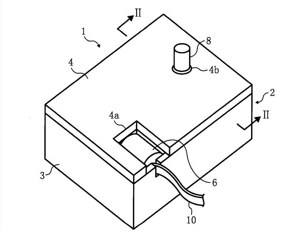
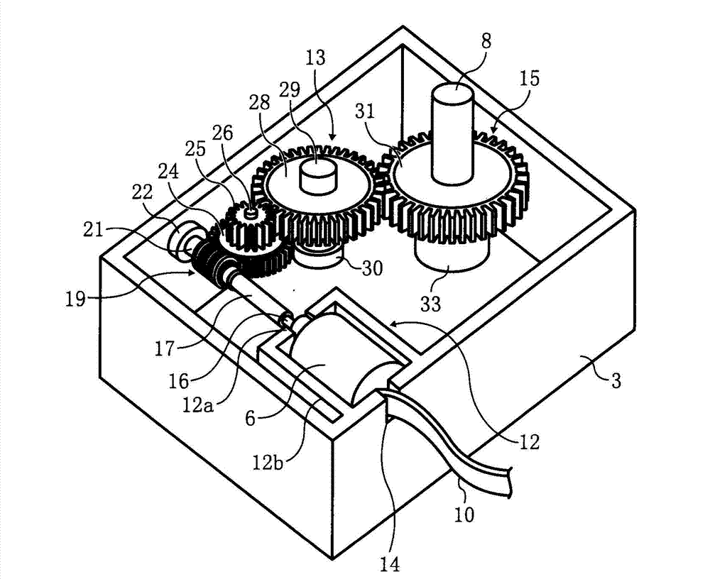
[0083] The driving device 1 according to the first embodiment of the present invention is as figure 1 and figure 2 As shown, a frame body 2, a motor 6 housed in the frame body 2 and used as a rotational power generating device for generating rotational power, and a motor 6 that is housed in the frame body 2 and used to transmit the rotation of the motor 6 are provided. The speed reducer 13 of the rotary power transmission mechanism of power, and the output gear 15 of the rotary power output mechanism which is accommodated in the frame 2 and outputs the rotary power transmitted from the above-mentioned speed reducer 13. The driving device 1 is formed in a size to be incorporated in an automobile, an OA machine, or the like.

[0084] The frame body 2 includes a cover plate 4 as one side of the frame body 2 and a body portion 3 as the other side of the frame body 2, and is for...

no. 2 approach

[0108] Next, referring to Figure 5- Figure 7 A second embodiment of the driving device 1 according to the present invention will be described. In addition, the code|symbol is attached|subjected to the same part as the said embodiment, and description is abbreviate|omitted.

[0109] In the driving device 1 according to the second embodiment of the present invention, as shown in FIG. The locking pieces 44 , 45 in the aforementioned pair of locking holes 41 , 42 . The motor 6 is embedded in the frame body 2 .

[0110] The locking holes 41 and 42 are provided on concentric circles of the output shaft 8 , and are formed in fan shapes symmetrical to each other with respect to the output shaft 8 . The locking holes 41 , 42 and the locking pieces 44 , 45 are in opposite directions relative to each other along the axial direction of the output shaft 8 after overlapping the plurality of frames 2 along the axial direction of the output shaft 8 . When rotating, the aforementioned loc...

no. 3 approach

[0124] Next, referring to Figure 8- Figure 11 A third embodiment of the driving device 1 according to the present invention will be described. In addition, the code|symbol is attached|subjected to the same part as the said embodiment, and description is abbreviate|omitted.

[0125] In the drive device 1 according to the third embodiment of the present invention, as shown in FIG. 8 , a pair of locking portions 48 and 49 are provided in the cover portion 4 . In the main body part 3, the locking pieces 44, 45 which are locked to the aforementioned pair of locking parts 48, 49 are protrudingly provided from the main body part 3 to the outside, and the locking pieces 44, 45 are protruded from the main body part 3 to the outside and are connected to the inner side. A pair of abutting protrusions 52, 53 that abut the cover portion 4. The motor 6 is embedded in the frame body 2 .

[0126] The locking parts 48 and 49 are formed in a frame shape, and include two bottom end parts ere...


PUM


Abstract

The invention provides a driving device capable of being carried in an OA machine etc. and effectively received in a conveying box. The driving device comprises a rotation power generation device (6) generating rotation power, a rotation power transmission mechanism (13) transmitting rotation power of the rotation power generation device (6), a rotation power output mechanism (15) outputting rotation power transmitted by the rotation power transmission mechanism (13), and a frame body (2) receiving the rotation power generation device (6), the rotation power transmission mechanism (13), and the rotation power output mechanism (15), an output shaft (8) performing perforation of one party of the frame body (2), the rotation power output mechanism (15) is supported by the shaft to protrude from the other party of the frame body (2) to the inner side of the frame body (2) and then be formed in a cylindrical shaft portion (33), furthermore, in the cylindrical shaft portion (33), a receiving concave portion (35) receiving an output shaft (8) when a plurality of frames (2) are in overlapping along the shaft direction of the output shaft (8).

Description

technical field [0001] The present invention relates to a driving device which is installed in OA equipment and the like and can be efficiently accommodated in a transport box. Background technique [0002] In OA equipment such as electrophotographic image forming apparatuses such as copiers, facsimile machines, and printers, motors and reducers are mounted as drive devices for driving paper feed trays that require a large torque. Integrated gear motor drive unit. [0003] This type of driving device includes a motor and a speed reducer that decelerates the rotational power of the motor and then transmits it. Scattering of grease applied to drive components inside the drive unit is prevented (see Patent Document 1). [0004] However, the drive device in the above-mentioned patent document protrudes from the frame because the output shaft connected to the above-mentioned push-up device etc. is protruded from the frame. Each independent storage space is defined, and the dri...

Claims


Application Information

Patent Timeline
Patent Type & Authority Applications(China)
IPC IPC(8): B41J23/02B41L21/00H04N1/00
Inventor 加藤伸一
Owner RICOH KK
Why Eureka
Try Eureka