Tensile testing device for architectural building blocks

A tensile test and construction technology, applied in the direction of applying stable tension/pressure to test the strength of materials, to achieve accurate test data and easy to use

Active Publication Date: 2015-02-18
WENZHOU UNIVERSITY
View PDF3 Cites 0 Cited by
  • Summary
  • Abstract
  • Description
  • Claims
  • Application Information

AI Technical Summary

Problems solved by technology

However, because the traditional tensile device does not fully consider the direction of the tensile force during stretching, the blocks often break due to the deflection of the force direction, and it is impossible to obtain accurate tensile force data, and the traditional tensile test device cannot accurately measure the specific position for force test

Method used


Image

  • Tensile testing device for architectural building blocks
  • Tensile testing device for architectural building blocks
  • Tensile testing device for architectural building blocks

Examples


Embodiment Construction

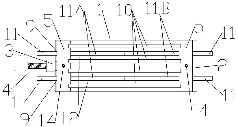
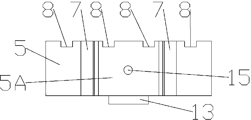
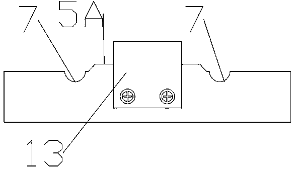
[0016] Such as figure 1 , figure 2 , image 3 , Figure 4 , Figure 5 , Figure 6 , Figure 7 As shown, the building block tensile test device provided by the present invention includes a base plate 1, one end of the base plate 1 is provided with a baffle plate 2, and the other end is provided with a screw mount 3, and the screw 4 passes through the threaded hole on the screw mount 3 , the two ends of the bottom plate 1 are respectively provided with an upper cover plate 5 and a lower cover plate 6 superimposed on each other, and the upper cover plate 5 and the lower cover plate 6 are respectively provided with an arc-shaped groove 7 and a plurality of side grooves 8, the upper cover After the plate 5 and the lower cover plate 6 are superimposed, the arc-shaped grooves 7 on both sides form the socket 9, and the side grooves 8 on the inner side of the upper cover plate 5 and the inner side of the lower cover plate 6 are aligned with each other to form a hole that runs th...


PUM


Abstract

A tensile testing device for architectural building blocks comprises a bottom plate. A retaining plate is arranged at one end of the bottom plate, a screw mounting seat is arranged at the other end of the bottom plate. A screw penetrates through a threaded hole on the screw mounting seat. An upper cover plate and a lower cover plate which are laminated mutually are arranged at the two ends of the bottom plate respectively. Arc grooves and a plurality of lateral grooves are arranged on the upper cover plate and the lower cover plate respectively. Inserting holes are formed by the arc grooves on two sides of the laminated upper cover plate and lower cover plate. Grooves penetrating through the upper cover plate and the lower cover plate are formed by mutually aligning the lateral grooves on the inner sides of the upper cover plate and the lower cover plate. Partitions are clamped on the relatively separated lateral grooves of the upper cover plate and the lower cover plate. Building block pouring grooves are formed by surrounding at least two partitions and the upper cover plate and the lower cover plate at the two ends. Shaft rods are inserted in the two inserting holes arranged oppositely. Each shaft rod comprises a left shaft rod and a right shaft rod. Ends of each left shaft rod and each right shaft rod are in inserting connection. Deviation of tension of a building block can be avoided, and a specific stress part on the building block can be controlled precisely.

Description

Technical field [0001] The invention involves a building stretch test device for building blocks. Background technique [0002] Traditional block stretching test devices generally include stretching and fixed end. By pulling the stretching end, the blocks are pulled and eventually broken. By studying the strength of the stretching and the broken of the block, the production of various materials is made of various materials.The block is tested.However, because the traditional stretching device is not fully considered when stretching, it is often broken due to the deflection of the direction of the force, and the accurate stretching data cannot be obtained.Putting the force test. Invention content [0003] The technical problem to be solved by the present invention is to provide a building stretching test device that can maintain the tension of the block without deflection and can accurately control the specific force parts on the block. [0004] To this end, the building provid...

Claims


Application Information

Patent Timeline
Patent Type & Authority Patents(China)
IPC IPC(8): G01N3/08
Inventor 孙林柱杨芳
Owner WENZHOU UNIVERSITY
Why Eureka
Try Eureka