Polarity-reversal signal converting method and device and display

A signal conversion device and polarity reversal technology, applied in static indicators, instruments, etc., to achieve the effect of flexible and changeable driving methods

Inactive Publication Date: 2012-11-21
BOE TECH GRP CO LTD +1
View PDF4 Cites 16 Cited by
  • Summary
  • Abstract
  • Description
  • Claims
  • Application Information

AI Technical Summary

Problems solved by technology

[0006] In view of this, the present invention provides a polarity inversion signal conversion method, device and display to solve the problem that the polarity inversion signal provided to the data driver cannot be changed according to different situations

Method used


Image

  • Polarity-reversal signal converting method and device and display
  • Polarity-reversal signal converting method and device and display
  • Polarity-reversal signal converting method and device and display

Examples


Embodiment 1

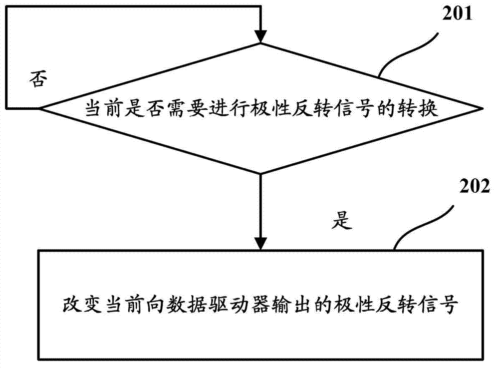
[0044] Such as figure 2 Shown is a schematic flowchart of a polarity inversion signal conversion method according to Embodiment 1 of the present invention, and the polarity inversion signal conversion method includes the following steps:

[0045] Step 201, judging whether it is necessary to convert the polarity inversion signal at present, if yes, execute step 202, otherwise, continue to execute step 201;

[0046] Step 202, changing the current polarity inversion signal output to the data driver.

[0047] Through the method provided by the above embodiments, the polarity inversion signal provided to the data driver can be changed according to different situations, so that the driving mode of the data driver is more flexible and changeable.

[0048] The first embodiment above will be described in detail below with an example.

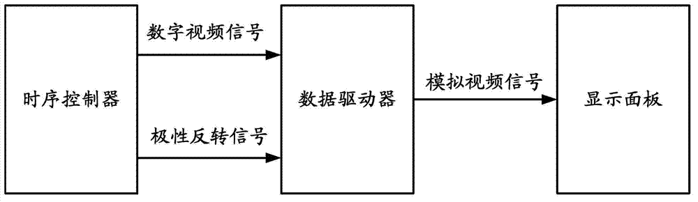
[0049] The existing timing controller usually drives the data driver in the dot inversion polarity driving mode and 1+2H dot inversion polarity drivi...

Embodiment 2

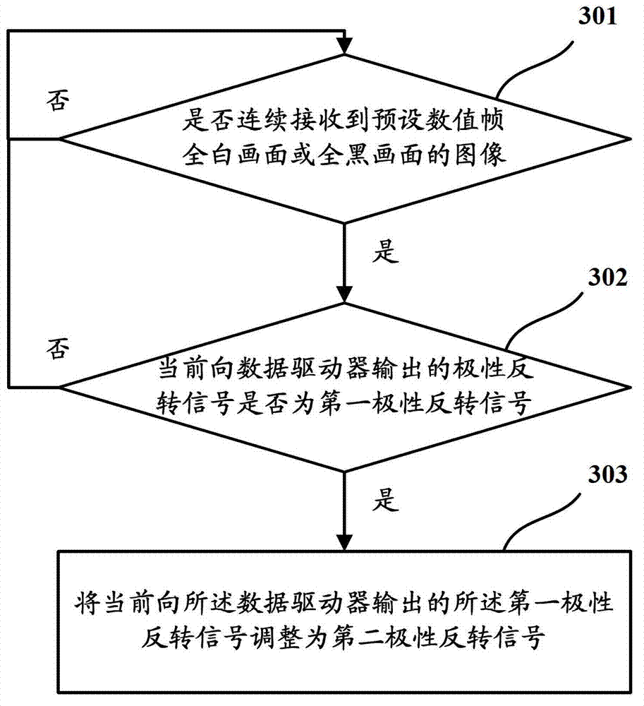
[0054] Such as image 3 Shown is a schematic flowchart of a polarity inversion signal conversion method according to Embodiment 2 of the present invention, and the polarity inversion signal conversion method includes the following steps:

[0055] Step 301, judging whether the image of the preset value frame full-white picture or full-black picture is continuously received, if yes, perform step 302, otherwise, continue to perform step 301;

[0056] In this embodiment, if images of the preset data frames are continuously received with an all-white picture or an all-black picture, it means that the display effect of the display is currently being tested.

[0057] The number of the preset values ​​can be set according to needs, for example, it can be 2 or 3.

[0058] Step 302, judging whether the polarity inversion signal currently output to the data driver is the first polarity inversion signal, if yes, execute step 303, otherwise, execute step 301;

[0059] Step 303, adjusting...

Embodiment 3

[0063] Such as Figure 4 Shown is a schematic flowchart of a polarity inversion signal conversion method according to Embodiment 3 of the present invention, and the polarity inversion signal conversion method includes the following steps:

[0064] Step 401, judging whether the images of the preset value frames of all-white or all-black frames are continuously received, if yes, execute step 402, otherwise, continue to execute step 401;

[0065] Step 402, judging whether the polarity inversion signal currently output to the data driver is the first polarity inversion signal, if yes, execute step 403, otherwise, execute step 401;

[0066] Step 403, adjusting the first polarity inversion signal currently output to the data driver to a second polarity inversion signal, wherein the data driver is in the polarity corresponding to the second polarity inversion signal The power consumption generated by driving in a polarity driving mode is smaller than the power consumption generated ...


PUM


Abstract

The invention provides a polarity-reversal signal converting method and device and a display. The polarity-reversal signal converting method comprises the steps of judging whether the conversion of a polarity-reversal signal is needed or not currently, generating a judgment result, and changing the polarity-reversal signal output to a data driver currently when the judgment result shows that the conversion of the polarity-reversal signal is needed currently. The polarity-reversal signal provided to the data driver can be changed according to different conditions, so that the driving mode of the data driver is more flexible.

Description

technical field [0001] The invention relates to the field of display technology, in particular to a polarity inversion signal conversion method, device and display. Background technique [0002] The liquid crystal molecules used in liquid crystal displays have a characteristic that the level of the pixel voltage applied across the pixel electrodes cannot be fixed all the time, otherwise the liquid crystal molecules will no longer be able to rotate in response to changes in the electric field because the characteristics have been destroyed to form Different shades of gray. In order to avoid the above situation, in the prior art, the pixel voltage is usually divided into two polarities (positive polarity and negative polarity). When the voltage of the pixel electrode is higher than the voltage of the common electrode, it is called positive polarity. When the voltage is lower than the voltage of the common electrode, it is called negative polarity. The direction of the liquid...

Claims


Application Information

Patent Timeline
Patent Type & Authority Applications(China)
IPC IPC(8): G09G3/36
CPCG09G3/3614
Inventor 许益祯李卫海孙志华汪建明张亮
Owner BOE TECH GRP CO LTD
Why Eureka
Try Eureka