Chemical waste residue and sludge drying device

A technology of sludge drying and drying equipment, which is applied in dehydration/drying/concentrated sludge treatment, waste fuel, petroleum industry, etc. It can solve the problems of increased wear, optimization, and small scale of drying equipment, so as to achieve easy maintenance, The effect of reducing drying cost and flexible driving mode

Pending Publication Date: 2021-12-07
SHAANXI YANCHANG CHINACOAL YULIN ENERGY CHEM
View PDF7 Cites 1 Cited by
  • Summary
  • Abstract
  • Description
  • Claims
  • Application Information

AI Technical Summary

Problems solved by technology

[0004] 1. The above-mentioned patents are mainly designed and developed for municipal sludge. The characteristics of the fine slag discharged from the coal gasification device cannot be fully considered in the design, and it cannot be optimized in combination with the original process conditions of the gasification device, resulting in investment in drying equipment. and higher operating costs
[0005] 2. The fine slag discharged from the coal gasification device contains a large amount of silica and alumina, so the hardness is extremely high. The drying equipment in the above patent (mainly through the paddle and drive shaft to move the slag) will aggravate its wear and tear and cannot be used for a long time. Stable operation
[0006] 3. The above-mentioned patents generally have a small drying equipment processing scale, which cannot meet the large-scale drying processing requirements of coal chemical enterprises

Method used


Image

  • Chemical waste residue and sludge drying device
  • Chemical waste residue and sludge drying device

Examples


Embodiment Construction

[0032] The present invention will be described in further detail below in conjunction with the accompanying drawings and embodiments. The examples are only used to explain the present invention, not to limit the protection scope of the present invention.

[0033] (1) Structural design and working principle of the drying device

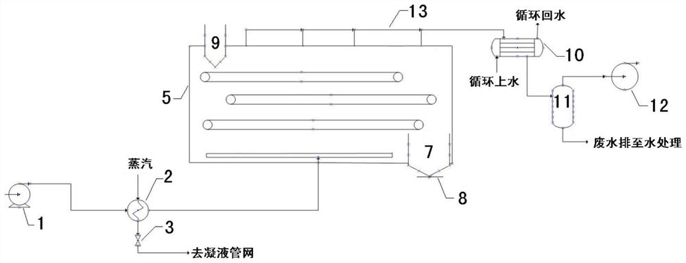
[0034] see figure 1 , The chemical waste residue and sludge drying device of the present invention mainly includes a hot air supply system, a material drying system and a hot air cooling system. The hot air supply system mainly includes a blower 1, an air heater 2 and a drainage facility 3, the air heater 2 is connected to the air outlet of the blower 1, and the air inlet of the blower 1 sucks outside air and pressurizes it and sends it into the air heater 2 , in the air heater 2, the inhaled air is heated by steam, and the obtained hot air is sent into the material drying system, and after the material (waste residue, sludge) is dried, a relatively ...


PUM


Abstract

The invention discloses a chemical waste residue and sludge drying device which comprises an air blower, an air heater, a hot air distributor, a feeding port, a multi-stage dynamic material distribution platform and a discharging port. Air is pressurized through the air blower and is conveyed to the air heater to be heated; Heated air is in contact with waste residues and/or sludge falling down along different levels of dynamic material distribution platforms in a baffling manner in the greenhouse from bottom to top, so that moisture is removed, and dry powder which can be directly combusted by equipment such as a boiler is obtained. The device is applied to the coal chemical industry, and solves the problems of high drying cost and poor drying effect of chemical waste residues and sludge.

Description

technical field [0001] The invention relates to the drying of waste residue in the gray water treatment section of a coal gasification device and the drying of sludge in a sewage treatment device. Background technique [0002] At present, enterprises generally use vacuum belt filter, plate and frame filter, and horizontal centrifuge to dehydrate the fine slag discharged from the coal gasification device, and send the dehydrated fine slag to the slag yard for landfill treatment. However, studies have shown that the carbon content of the fine slag produced in the coal gasification process is as high as 50% (dry basis). Direct landfill treatment not only causes a serious waste of resources, but also requires a large amount of investment in slag field construction, haulage and leachate treatment. , occupying a large amount of corporate funds. At the same time, the sludge produced by these enterprises in the production of sewage treatment also needs to be dried. [0003] Since ...

Claims


Application Information

Patent Timeline
Patent Type & Authority Applications(China)
IPC IPC(8): C02F11/13C10L5/46
CPCC02F11/13C10L5/46Y02E50/10Y02E50/30
Inventor 瞿磊陈昱李佐鹏江莉莎王涛秦超李永华李文虎丁海洋张博任鹏
Owner SHAANXI YANCHANG CHINACOAL YULIN ENERGY CHEM
Why Eureka
Try Eureka